- #1
oho11
- 14
- 1
- TL;DR Summary
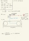
- I have a gear and sprocket machine with the details of the motor and want to see if it will be enough or I need something more
Hi everyone!
I am in a bit of a halt right now as I don't really know where to begin with this problem,
There is a chain and sprocket machine that I have the details of the motor of and majority of the dimensions of but I don't know how to start, I tried to look at some of the posts on here but I still feel a bit confused, I have attached some photos of the information I have and what I have done so far which I know is not much but hence why I wanted to come on here and ask for help,
KEEP IN MIND I am not asking for it to be solved or anything, I simply want to learn about mechanics and would appreciate some foundation on where to start from and work my way up, I have taken some courses but I don't fully know everything that needs to be taken into consideration of hence why I am glad to find this website since a lot of people seem to be very helpful
If there is any additional information required please let me know and I will get them for you since I am not sure what other dimensions might be needed,
Thanks in advance!