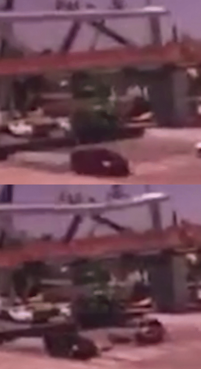
FIU pedestrian bridge install left it vulnerable to collapse, WTH

In summary, the pedestrian bridge in Miami that collapsed Thursday had only been put in place on Saturday under a process that allowed for installation of large sections — but that experts said left it vulnerable to collapse until it was complete.
  • #36
jim hardy said:
It gets curioser and curioser.
might not have been a tensioner in it? sure looks like one in the rubble...
This is from the proposal so not an "As Built" drawing..
http://facilities.fiu.edu/projects/BT_904/MCM_FIGG_Proposal_for_FIU_Pedestrian_Bridge_9-30-2015.pdf
View attachment 222347

so we'll have to wait on the trickle of information.

@Baluncore - that AVE youtube video pointed out when they lifted the span that end was cantilevered - wouldn't that put north-most diagonal #11 in tension?

Hopefully somebody made provision for the "As Lifted" transporter arrangement...

View attachment 222348

Sigh. Old troubleshooter just can't let go. I grew up about five miles from there.

old jim
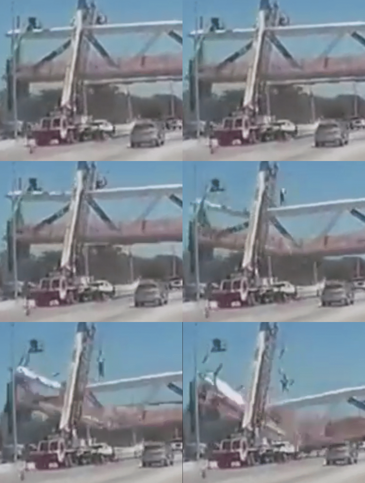
So if they forgot to tension 11 when they changed the lifting plan that would account for the report of "slack cables" and cracking.
 
Engineering news on Phys.org
  • #37
jim hardy said:
@Baluncore - that AVE youtube video pointed out when they lifted the span that end was cantilevered - wouldn't that put north-most diagonal #11 in tension?

That looks right, what happens if it is in tension?

Thanks!
 
  • #39
boneh3ad said:
It does appear that the failure began on the north end. That doesn't necessarily mean it has anything to do with the cracks. For all we know, "cracks" may have been purely cosmetic.
I have been unable to discover the pictures again - perhaps it was on a news report, but to me it appeared that the majority of reinforcement rods were going in the wrong direction. Since this was just a flash observation I couldn't be sure. Also the way that the concrete shattered suggests little to no reinforcement in areas. One of the ways that they take old concrete buildings down is to break them apart sufficiently to remove the reinforcing steel rods and then they put the sections of concrete through a grinder to make pebbles that can be trucked away. There was a very large area reduced to these pebbles. This suggests to me that it was either insufficiently reinforced or the concrete mixture was incorrect.

Another thing - this was supposedly going to be suspended. So why didn't they put the suspension pillar up first? One of the things I have a real problem with is a design in which there was a light directly in front of this bridge which forced traffic to stop and wait underneath and/or to be moving at a slow rate of speed. To my mind these sorts of crosswalk bridges are supposed to be away from this sort of thing. We have some of these sorts of bridges around the San Francisco area and they are all away from areas there traffic might congregate.
 
  • #40
Concrete is strong on compression but weak in tension. If necessary any beams that might be in tension are put into compression by pre or post tensioning rods inside the concrete. In this case the beams were post tensioned using hydraulic rod tensioners.

What follows is reasonable speculation until more is known...

It looks like they calculated beam 11 didn't need to be post tensioned, presumably because they thought it would be in compression while rhe bridge was moved and when the bridge was fully errected.

However when the lifting tressle was moved inboard this caused the north end to be cantilevered and beam 11 to be in tension, possibly causing the reported cracking?

My guess is they realized beam 11 was in tension when investigating the cracks and were trying to post tension it when it failed.
 
  • Like
Likes jim hardy
  • #41
Tom Kunich said:
One of the things I have a real problem with is a design in which there was a light directly in front of this bridge which forced traffic to stop and wait underneath and/or to be moving at a slow rate of speed. To my mind these sorts of crosswalk bridges are supposed to be away from this sort of thing. We have some of these sorts of bridges around the San Francisco area and they are all away from areas there traffic might congregate.

That certainly sounds like a reasonable measure to take in an earthquake area.
 
  • #42
In the discussion above, there is frequent discussion of "beam xxx being in tension/compresson." This is loose terminology. The concrete should always be in compression and the reinforcement always in tension, even though these are coaxial. Thus to speak of "beam xxx" as being in tension is unclear; are you saying that, for this beam, the concrete is in tension or the steel is in tension? Each of these members will be in compression in the concrete and in tension in the steel, if all is correct.
 
  • Like
Likes jim hardy and CWatters
  • #43
Cheryl Stopnick, an outside spokeswoman for FIGG Bridge Engineers, which designed the bridge, said the structure was “truss bridge with above-deck truss elements.”

Robert Accetta, the National Transportation Safety Board investigator in charge, said diagonal elements between the bridge’s canopy and deck worked like a truss bridge. But the cables designed to fan out from the column weren’t needed to support the bridge deck, he said.

“As I understand it, these were cosmetic,” Accetta said. “They were not structural members.”
https://www.usatoday.com/story/news...se-suspension-cables-support-tower/431418002/

Tom Kunich said:
Another thing - this was supposedly going to be suspended. So why didn't they put the suspension pillar up first? One of the things I have a real problem with is a design in which there was a light directly in front of this bridge which forced traffic to stop and wait underneath and/or to be moving at a slow rate of speed. To my mind these sorts of crosswalk bridges are supposed to be away from this sort of thing. We have some of these sorts of bridges around the San Francisco area and they are all away from areas there traffic might congregate.
 
  • #44
Dr.D said:
In the discussion above, there is frequent discussion of "beam xxx being in tension/compresson." This is loose terminology. The concrete should always be in compression and the reinforcement always in tension, even though these are coaxial.

Understood.

Some of the documents (see post #35) appear to show there were no reinforcement bars in elements 9 and 11-14 and hence there is no value for the "P.T force/bar" in the table for those elements. This suggests they weren't expecting these elements to be subject to tension loads but tension loads may have occurred when they changed how the bridge was moved into place.

To add confusion photos appear to show there were bars in element 11. Perhaps they put bars in element 11 "just in case" but never tensioned them because they thought they weren't needed because they always expected compression loads?
 
  • #45
Dr.D said:
In the discussion above, there is frequent discussion of "beam xxx being in tension/compresson." This is loose terminology. The concrete should always be in compression and the reinforcement always in tension, even though these are coaxial. Thus to speak of "beam xxx" as being in tension is unclear; are you saying that, for this beam, the concrete is in tension or the steel is in tension? Each of these members will be in compression in the concrete and in tension in the steel, if all is correct.

Mea Culpa, what happens when electricals try to wet their feet in civil engineering.
I was speaking of the net force on the diagonal element.
It appears to me that during transport #11 would be under tension. If #11 has inside itself a tensioning rod that was tensioned to keep the concrete in compression - no problem .
......
IF indeed during transport #11 DID experience tension,
AND IF it had no internal pretensioning rod
THEN i see how it could have suffered damage, for its internal rebars would have had to counteract the tension and that requires stretching them.

Would a beam that had been subjected to that stretch be prone to buckling upon return to compression loading ?

Please excuse my clumsiness with terms - i hope i conveyed that thought unambiguously.

CWatters said:
To add confusion photos appear to show there were bars in element 11. Perhaps they put bars in element 11 "just in case" but never tensioned them because they thought they weren't needed because they always expected compression loads?

That's the 64 dollar question to me right now.
Was #11 built per that preliminary drawing without a tensioning rod to keep the concrete in compression under tensile load?
If not, did cantilevering that end of the beam edit bridge during transport apply tension to diagonal #11 ?

Right now that remains a hypothetical mechanism for failure. The hypothesis needs to be held up against as-built drawing, and if diagonal #11 was tensioned how much and when.
Then it can be pursued farther or discarded.

They've sure been quiet about what where how much and when was tensioned.

That's troubleshooting - rule out possibilities one at a time.

old jim
 
Last edited:
  • #46
Interesting composite animations from forum..

https://www.eng-tips.com/viewthread.cfm?qid=436595

output_jdjfnF_ckjo6r.gif

I think this one may have some video artifacts/pixilation that might be misleading..
output_pG013O_iwl4xz.gif
 
  • #47
CWatters said:
My guess is they realized beam 11 was in tension when investigating the cracks and were trying to post tension it when it failed.
But beam 11 was only in tension during the move. I notice some reinforcing steel showing in the crushed concrete and I would expect that steel to support the weight of the short cantilever during transport. Any cracks that did open in member 11 during transport would have closed when it was seated.

The situation changed completely when the truss was positioned and seated on the end points only. Then members 2 and 11 would be under their highest compressive load, along with the top plate. Once that situation was present, any tendon under tension in member 11 would be a liability as it would increase the total load carried by the concrete in 11, without advantage. I suspect that was why no PT bar tendons were specified for member 11 in the original proposal.

My concern is then with the junction of member 11 and the top plate. At that point the compression in 11 must be spread from the solid junction block of 10 and 11, out into the wide thin section of the top plate. As I see it, that stress concentration in the top plate will then be the vulnerable point.

The low frame rate car video shows member 11 failing high up, close to the solid junction block. It did not fail near the centre as I would expect with a column stability problem. Nor was it first to fail. I take that to indicate a failure in the top plate, very close to the 10, 11 junction block, that then broke member 11 close to the rigid junction block.

The crushing failure of the top plate is very rapid. The top plate near the 10, 11 junction block accelerates downwards at greater than one G, as is evident by the unfortunate operator = valuable witness, on the top plate, stretching from a crouch to full length as the top plate is forced downwards by the centre of mass of the main truss.

There is still the wave and shudder present in the top plate that plays an important part in the failure sequence. That wave is seen only in the high frame rate TV, not in the car-cam video.
 
  • Like
Likes CWatters, Spinnor, jim hardy and 1 other person
  • #48
Baluncore said:
There is still the wave and shudder present in the top plate that plays an important part in the failure sequence. That wave is seen only in the high frame rate TV, not in the car-cam video.

Hmmm. i'd been looking for that ever since you mentioned it a day or two ago.
Per the proposal the vertical resonance is raised to >3hz by the overhead stays that weren't yet there . I've not found what it is without them.
Horizontal is >1.3hz
page 63 of the proposal pdf
upload_2018-3-20_19-38-28.png
 

Attachments

  • upload_2018-3-20_19-38-28.png
    upload_2018-3-20_19-38-28.png
    13.8 KB · Views: 585
  • #49
Those natural frequency specs are intended to guard against resonance due footsteps, wind vortex shedding, and various other excitations. They really tell us next to nothing about the static situation (I've not seen any mention at all of high winds or other environmental excitations). Further, I'm pretty sured that they are intended to apply to the completed structure, not to the half-built assembly. It was never really completed, so we'll never see those conditions at work.
 
  • Like
Likes jim hardy
  • #50
http://www.miamiherald.com/news/local/community/miami-dade/west-miami-dade/article206122229.html
Steel-truss bridges have been commonly used in roadway construction going back decades. But they have a well-known vulnerability: If a vehicle hits one of the horizontal support trusses, the entire span can collapse.

That’s what happened in the 2013 collapse of a 1955 steel-truss bridge over the Skagit River on Interstate 5 near Seattle: A truck carrying an oversized load struck supporting steel struts along one side of a bridge span, which split apart and fell into the river. That’s because there were no backup or redundant structural elements to support the span if one piece failed.
...
His source is not clear. But the Associated Press said in a story Tuesday that the Florida Department of Transportation ordered the northern support pylon be moved 11 feet to make room for future expansion of the trail. That required a design change that lengthened the span — and put the support pylon in the dirt well off the edge of the roadway, which could also explain why the northernmost truck could no longer follow its original planned route.
 
  • Like
Likes Spinnor
  • #52
member 11 from youtube , B1PPqa9cS-k

fiubridge18.jpg
 

Attachments

  • fiubridge18.jpg
    fiubridge18.jpg
    29.2 KB · Views: 605
  • #53
from NTSB video at youtube.com/watch?v=aeJKqojmHgY&feature=youtu.be&t=1m25s
looks like there were tensioning rods in #11

fiubridge19.jpg


so that question is answered...
 

Attachments

  • fiubridge19.jpg
    fiubridge19.jpg
    28.5 KB · Views: 644
  • #54
  • Like
Likes jim hardy

Similar threads

Replies
43
Views
9K
  • MATLAB, Maple, Mathematica, LaTeX
Replies
1
Views
3K
Back
Top