Calculate current through tank circuit on induction heater

  • #1
imsmooth
152
13
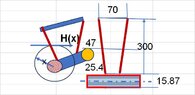
I want to measure tank circuit currents using *different* methods. Below is the tank circuit. The coupling transformer has 20 turns and has 10A @ 80khz going through it. This means there should be a maximum of 200A in the tank (20:1 turns ratio). I measure the voltage across the 2.6uF capacitor and get about 150 Vrms. With a capacitative reactance of about 0.75R this equals 200A.

I now want to measure the voltage across 1 inch (25.4mm) of the 1/2" copper tubing (TEST, mislabeled as 2") that serves as the conductor for the tank. The tubing has an outside diameter of 15.975mm. With a skin effect of .2mm @80kHz I get:

R = p*L/A
A = pi/4 * (15.875^2 - 15.475^2)
L = 0.0254m, A = 0.00000984m^2, p = 1.7x10⁻⁸ R-m

This gives R = 0.000044R

When I measure the voltage across 1 inch of pipe under the same conditions I get 3.4Vrms.

A = V/R which would be over 700,000A. This can not be correct. What am I missing?

NOTE: voltage measurements are done with oscilloscope
circuit.jpg
 
Last edited by a moderator:
Engineering news on Phys.org
  • #2
imsmooth said:
The coupling transformer has 20 turns and has 10A @ 80khz going through it. This means there should be a maximum of 200A in the tank (20:1 turns ratio). I measure the voltage across the 2.6uF capacitor and get about 150 Vrms.
Holy cow. So your tank circuit is about 150V @10A and 80kHz? What in the world are you doing with this?
 
  • #3
berkeman said:
So your tank circuit is about 150V @10A and 80kHz? What in the world are you doing with this?
That is mythical circulating energy.

imsmooth said:
A = V/R which would be over 700,000A. This can not be correct. What am I missing?
imsmooth said:
This gives R = 0.000044R
Don't forget to add the series resistance of the capacitor when calculating the tank resistance.
 
  • #4
I don't want the resistance of the tank. I want the resistance of the 1 inch segment and current through it. My question is about the discrepancy between my measurements.

Am I making the TEST voltage measurement incorrectly?
 
  • #5
berkeman said:
Holy cow. So your tank circuit is about 150V @10A and 80kHz? What in the world are you doing with this?
No. The capacitor and work coil voltages cancel. The actual voltage across the coupling transformer is much lower. The current, thought, is very high.

I'm doing it just to understand how these things work...and to heat metal.
 
  • #6
Is the oscilloscope probe grounded or differential? There is some magnetic flux in the signal which is not surprising. Can you draw earth grounds on your test sketch?
 
  • #7
I was using a differential probe. The tank is floating and not grounded.
 
  • Like
Likes hutchphd
  • #8
imsmooth said:
I don't want the resistance of the tank. I want the resistance of the 1 inch segment and current through it. My question is about the discrepancy between my measurements.

Am I making the TEST voltage measurement incorrectly?
Attach two thin wires to the conductor as the test leads. Run one wire along the conductor doing a single turn, then twist the two wires closely together. Place a couple of ferrite toroids on the twisted pair as common mode chokes. That will eliminate any test-lead loop area that may generate a stray voltage.
 
  • Like
Likes Dullard and hutchphd
  • #9
In my opinion it is about the circuit reactance.
Tank reactance.jpg
 
  • Like
Likes tech99
  • #10
  • #11
Babadag said:
In my opinion it is about the circuit reactance.View attachment 342651
This correlates with what I measured. What formula is this?
 
  • #12
imsmooth said:
This correlates with what I measured.
But when measuring current, you want real resistance only, you do not want to include reactance in the shunt.
In post #8, I explained how to eliminate the inductance of the wire from the voltage drop across the resistance. You need to minimise the area of the meter connection loop.
 
  • Like
Likes Babadag, Tom.G and DaveE
  • #13
(I hope the message is quoted)
No it isn't. Well I am replying to @Babadag

I am sorry but could you please explain what you did here?
The way I would go is to compute the magnetic field generated by the large current in the pipe circuit, then compute the flux intercepted by the measurement loop by surface integration, and convert its time derivative into the EMF that will almost entirely appear across the voltmeter.

But you seem to compute the inductance of... What exactly? The lengths seem those of the measurement loop, but the current is that of the copper pipe circuit.

What am I missing?
 
  • #14
Since Windows 11 up-dating it produces chaos -usually,
I had to revise my calculation.
The inductance formula is incomplete.
Theoretically, the magnetic field around a conductor where a current flow is
H=I/(2*pi()*x) [A/m] if x is the radius from conductor centre line up toany point outside.
B=μo*H the magnetic flux density [Wb/m^2]
dφ=B*length*dx
dφ=μo*H*length*dx
dφ=μo*I/(2*pi()*x)*length*dx
φ=μo*I/(2*pi()ln(xmax/xo)*length.[Wb]
If xo=D/2 and xmax=300+D/2 then:
φ=μo*I/(2*PI())*LN(xmax/xo)*length
μo=4*pi()/10^7 [H/m]
L= φ/I= μo /(2*PI())*LN(xmax/xo)*length [H] total magnetic flux through area.
If length=(my appreciation) 47 mm average then:
L=4*pi()/10^7/2/pi()*ln((300+15.87/2)/(15.87/2))*47/1000 = 3.43909E-08 H
Reactance=2*pi()*f*L=2*pi()*80*10^3*3.439/10^8 = 0.017286747 ohm
Voltage drop VD=196*0.01729= 3.388202414 V
[neglecting the resistances]
 

Attachments

  • Current flows though tank.jpg
    Current flows though tank.jpg
    24.7 KB · Views: 5
  • #15
Thank you @Babadag ,

My problem is with this part of your computation

L= φ/I

Where, it appears, φ is the flux in the measurement loop, while I is the current in the copper pipe branch alone.
Are you using some partial inductance mathematical 'trick'?
 
  • #16
Baluncore said:
You need to minimize the area of the meter connection loop.
I tried to do what you said and you are correct. When I create a smaller measurement loop the measured voltage goes down. It seems like it would be very difficult at these frequencies to just measure the conductor's resistance without the added inductive impedance.
 
  • #17
I guess it's not possible to edit previous posts to add something (after some time)?

Anyway, I guess babadag converted the surface integral of B into the line integral of A and then only considered the leg with the most current.
 
  • #18
The only thing that can be considered a “mathematical trick” it is the shape and dimensions of the measuring loop where the only thing precise is the distance on the tank, the rest is my fantasy.
 
  • #19
imsmooth said:
It seems like it would be very difficult at these frequencies to just measure the conductor's resistance without the added inductive impedance.
Then you have not realised how one wire twisted about another can cancel the loop area.
 
  • #20
Baluncore said:
Then you have not realised how one wire twisted about another can cancel the loop area.
I've twisted the differential probe wires. I'll try to put more twist on them.
 
  • #21
Baluncore said:
Attach two thin wires to the conductor as the test leads. Run one wire along the conductor doing a single turn, then twist the two wires closely together. Place a couple of ferrite toroids on the twisted pair as common mode chokes.
What do you mean by "doing a single turn"? Are you saying to twist the test leads and then wrap the pair around the toroid? The single-turn with one of the leads is throwing me off.
 
  • #22
imsmooth said:
I'll try to put more twist on them.
For wavelengths longer than the shunt, you only need one turn around each straight segment of the shunt. If the shunt is a braid, you can pass the meter-wire up the middle of the braid, like the core of a coaxial cable.
 
  • #23
Baluncore said:
For wavelengths longer than the shunt, you only need one turn around each straight segment of the shunt. If the shunt is a braid, you can pass the meter-wire up the middle of the braid, like the core of a coaxial cable.
Any chance you could sketch this?
 
  • #24
Maybe this sketch will help. Keep the wire close to the shunt. Then the twisted pair goes to the voltmeter for current computation.

shunt_voltmeter.jpg
 
  • Like
Likes Babadag
  • #25
I thought this is what you meant. Why the single turn from the lead on the left? Why not have both test leads meet midway in the section under test and start twisting there?
 
  • #26
imsmooth said:
Why the single turn from the lead on the left?
You have one turn over each short length, and pull it tight, so it does not pick up local EMI.

imsmooth said:
Why not have both test leads meet midway in the section under test and start twisting there?
You can do that, but usually you have the meter at one end of the resistor.
 
  • #27
Did a lot of twisting and used a common mode choke. I was able to get the measured voltage down from 3.4v to 0.5v. This gives a current of about 38,000A which is still more than the 200A I should have measured. It seems that even the slightest stray inductance throws off this method of measuring current.
 
  • #28
How about you insert a piece of pipe made of a less conducting material, such as iron or better yet stainless steel (which has much higher resistivity)? And then use that as a shunt to measure the voltage drop of? What is the EMF of one turn around the toroid?

On second thought, even if you manage to create a thin steel pipe section capable of dropping 1V, you will need to dissipate 200W in it. Might run a little too hot.

Try to measure the voltage without connecting the voltmeter's probes to the copper pipe, but only to a separated piece of wire very close to it, in order to find the induced EMF and compare with the measurement that includes the ohmic drop (probes tips on pipe). Do you see a discernible difference?
 
Last edited:

Similar threads

Replies
7
Views
2K
  • Electrical Engineering
Replies
21
Views
1K
Replies
10
Views
1K
Replies
2
Views
964
Replies
2
Views
2K
  • Electrical Engineering
Replies
6
Views
2K
  • Electrical Engineering
Replies
5
Views
1K
  • Electromagnetism
Replies
16
Views
1K
  • Electrical Engineering
Replies
9
Views
3K
Replies
20
Views
2K
Back
Top