- #1
You are using an out of date browser. It may not display this or other websites correctly.
You should upgrade or use an alternative browser.
You should upgrade or use an alternative browser.
The multimeter is not displaying mv of strain gauge in circuit
- I
- Thread starter Micheal_Leo
- Start date
-
- Tags
- Multimeter Strain gauge
In summary: Thank you very much, hx711 supplying voltage is 5v, i shoud use dc power supply and give 1.5v to both hx711 and wheatstone brdige
Physics news on Phys.org
- #2
Baluncore
Science Advisor
2023 Award
- 14,497
- 8,411
You have an overload on the mV scale. Switch to DC volts to see what voltage you have.Micheal_Leo said:... but multimiter is not displaying anything ...
Please provide the circuit you are using with all resistor values.
What is the resistance of the strain gauge?
- #3
Micheal_Leo
- 63
- 4
Baluncore said:You have an overload on the mV scale. Switch to DC volts to see what voltage you have.
Please provide the circuit you are using with all resistor values.
What is the resistance of the strain gauge?
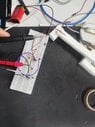
please find the attached schematic diagram
Attachments
Last edited by a moderator:
- #4
Baluncore
Science Advisor
2023 Award
- 14,497
- 8,411
The resistor ratios must match.
Is that a pair of 220R = 220 ohm resistors in the top row, making half the supply ?
Below left is another 220R resistor, but it should match the 120 ohm strain gauge, so it also makes about half the supply. Then mV range should work.
Replace the bottom left 220R with a 120R resistor.
Is that a pair of 220R = 220 ohm resistors in the top row, making half the supply ?
Below left is another 220R resistor, but it should match the 120 ohm strain gauge, so it also makes about half the supply. Then mV range should work.
Replace the bottom left 220R with a 120R resistor.
- #5
Micheal_Leo
- 63
- 4
yes half supply,i do not have 120 ohm resistors,.can i use 100+ 22 ohm resistors in series?Baluncore said:The resistor ratios must match.
Is that a pair of 220R = 220 ohm resistors in the top row, making half the supply ?
Below left is another 220R resistor, but it should match the 120 ohm strain gauge, so it also makes about half the supply. Then mV range should work.
Replace the bottom left 220R with a 120R resistor.
- #6
berkeman
Mentor
- 67,144
- 20,080
Why are you using such a high bias voltage? Maybe switch to a single 1.5V AA battery to avoid wasting so much power...Micheal_Leo said:please find the attached schematic diagram
- #7
Micheal_Leo
- 63
- 4
berkeman said:Why are you using such a high bias voltage? Maybe switch to a single 1.5V AA battery to avoid wasting so much power...
actually i have limited resources so have to do in limit resource
Last edited by a moderator:
- #8
Baluncore
Science Advisor
2023 Award
- 14,497
- 8,411
Yes.Micheal_Leo said:yes half supply,i do not have 120 ohm resistors,.can i use 100+ 22 ohm resistors in series?
- #9
Micheal_Leo
- 63
- 4
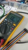
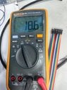
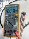
THE Attached results are mv and Voltage , please see this , i will connect it to hx711, these results before force not applied , please guide that should i consider mv or voltage to transfer it to arduino to study stress in that part.the PLA printing material not follow hookes law i have applied force on part for testing so little bending is present in partBaluncore said:Yes.
Attachments
- #10
Baluncore
Science Advisor
2023 Award
- 14,497
- 8,411
I do not know where you are going with this.
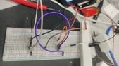
Do you see any change in the mV reading when you flex the strain gauge?
If you see only a small change, you may need to adjust the 22R resistor, to better balance the bridge, to get closer to a zero difference voltage output. Then you can use more gain in the hx711 without the amplified DC offset hitting the voltage limits.
The differential voltage output that now goes to your mV meter, will go to the hx711 differential inputs, INA+, INA-. The bridge drive voltage will probably come from the hx711, AVDD and AGND.
- #11
Micheal_Leo
- 63
- 4
i see change in mv but also my finger burn accidently comes near to strain gauge , strain gauge get hot during this phenomena mv voltage out of control like it kept increasing ,Baluncore said:I do not know where you are going with this.
Do you see any change in the mV reading when you flex the strain gauge?
If you see only a small change, you may need to adjust the 22R resistor, to better balance the bridge, to get closer to a zero difference voltage output. Then you can use more gain in the hx711 without the amplified DC offset hitting the voltage limits.
The differential voltage output that now goes to your mV meter, will go to the hx711 differential inputs, INA+, INA-. The bridge drive voltage will probably come from the hx711, AVDD and AGND.
should i give 5V , right now i am giving 9V
- #12
Baluncore
Science Advisor
2023 Award
- 14,497
- 8,411
Too much voltage to the bridge circuit.Micheal_Leo said:... i see change in mv but also my finger burn accidently comes near to strain gauge ...
Too much bridge current.
Too much heating of the strain gauge resistance.
The gauge resistance is temperature dependent, so balance changes.
Use less voltage, use AVDD and AGND from the hx711.
- #13
Micheal_Leo
- 63
- 4
thank you very much, hx711 supplying voltage is 5v, i shoud use dc power supply and give 1.5v to both hx711 and wheatstone brdigeBaluncore said:Too much voltage to the bridge circuit.
Too much bridge current.
Too much heating of the strain gauge resistance.
The gauge resistance is temperature dependent, so balance changes.
Use less voltage, use AVDD and AGND from the hx711.
- #14
Baluncore
Science Advisor
2023 Award
- 14,497
- 8,411
The hx711 can run on between 3 and 5 V. If you use the same voltage as your controller, the digital signal voltages will all match without problems.
The hx711 has a regulator that provides the voltage drive to the bridge. The voltage is set by the ratio of R1 and R2 on the hx711 reference PCB design in the data sheet. Use what it has now, or select resistors that set the bridge voltage to somewhere between 1.2 and 2.5 volts.
The hx711 has a regulator that provides the voltage drive to the bridge. The voltage is set by the ratio of R1 and R2 on the hx711 reference PCB design in the data sheet. Use what it has now, or select resistors that set the bridge voltage to somewhere between 1.2 and 2.5 volts.
- #15
Micheal_Leo
- 63
- 4
i have voltage regulator so have intention to supply 3v to both bridge and hx711Baluncore said:The hx711 can run on between 3 and 5 V. If you use the same voltage as your controller, the digital signal voltages will all match without problems.
The hx711 has a regulator that provides the voltage drive to the bridge. The voltage is set by the ratio of R1 and R2 on the hx711 reference PCB design in the data sheet. Use what it has now, or select resistors that set the bridge voltage to somewhere between 1.2 and 2.5 volts.
- #16
Baluncore
Science Advisor
2023 Award
- 14,497
- 8,411
If you increase the bridge drive voltage by 1%, you get a 1% increase in the difference voltage from the bridge, for the same strain. That is a problem with accurate 24 bit measurements.Micheal_Leo said:i have voltage regulator so have intention to supply 3v to both bridge and hx711
The A-D converter is ratiometric. It uses the bridge drive voltage as a full-scale reference, and so automatically corrects for variations. That is why it has the voltage regulator for the bridge drive on the same chip as the A-D converter. If you do not use that on-chip regulator, you will get scale errors in the strain readings. Read the data sheet, and follow the advice.
- #17
Micheal_Leo
- 63
- 4
please can you suggest best A-D converterBaluncore said:If you increase the bridge drive voltage by 1%, you get a 1% increase in the difference voltage from the bridge, for the same strain. That is a problem with accurate 24 bit measurements.
The A-D converter is ratiometric. It uses the bridge drive voltage as a full-scale reference, and so automatically corrects for variations. That is why it has the voltage regulator for the bridge drive on the same chip as the A-D converter. If you do not use that on-chip regulator, you will get scale errors in the strain readings. Read the data sheet, and follow the advice.
- #18
Baluncore
Science Advisor
2023 Award
- 14,497
- 8,411
You cannot afford the best.Micheal_Leo said:please can you suggest best A-D converter
Use the hx711, because it is available, cheap ($2), and comes mounted on a PCB.
- #19
Micheal_Leo
- 63
- 4
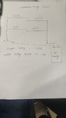
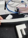
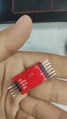
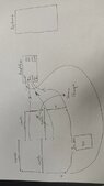
i have try to do it , somehow it work as i expected , the video attached , secondly the follwoing hx711 amplifier i have , i am very much confused how to attach wheatstone bridge with this hx711 , please need your guidanceBaluncore said:You cannot afford the best.
Use the hx711, because it is available, cheap ($2), and comes mounted on a PCB.
video about strain gauge and wheatstone bridge
i have try to draw diagram of connecting , please check
Attachments
Last edited:
- #20
Baluncore
Science Advisor
2023 Award
- 14,497
- 8,411
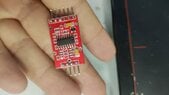
I think, in the Weixin picture, at the analogue end of the PCB ...
A+ and A- are the bridge output terminals, (your old meter connections).
GND is probably analogue ground to the bridge.
Out+ is the regulated power to the bridge.
You can check those by following the terminals to the chip pins.
Do you have a copy of the hx711 data sheet?
It shows the connections to the bridge on page 1, fig 1. Also page 6, fig 4.
https://cdn.sparkfun.com/datasheets/Sensors/ForceFlex/hx711_english.pdf
Similar threads
-
Other Physics Topics
- Replies
- 3
- Views
- 994
- Replies
- 77
- Views
- 4K
-
Electrical Engineering
- Replies
- 24
- Views
- 2K
-
Electrical Engineering
- Replies
- 6
- Views
- 878
-
Other Physics Topics
- Replies
- 1
- Views
- 1K
-
Electrical Engineering
- Replies
- 8
- Views
- 857
-
Classical Physics
- Replies
- 1
- Views
- 535
-
Mechanical Engineering
- Replies
- 5
- Views
- 1K
-
Electrical Engineering
- Replies
- 3
- Views
- 2K
-
General Engineering
- Replies
- 2
- Views
- 2K
Share: