
A New Interpretation of Dr. Walter Lewin’s Paradox
Much has lately been said regarding this paradox which first appeared in one of W. Lewin’s MIT lecture series on ##{YouTube}^{(1)}##. This lecture was recently critiqued by C. Mabilde in a second YouTube video and submitted as a post in a PF ##{thread}^{(2)}##. The latter cited the third source, that of K. T. McDonald of Princeton University, as support for Mabilde’s ##{presentation}^{(3)} {and}^{(4)}##. Finally, Charles Link, PF Homework Helper, and Insight Author posted in Advisory Lounge Inner Circle (#1, May 25, 2018) on the same subject. Furthermore, several other PF individuals (and probably others still) have been involved in this topic.
I think a key concept, which none of the three sources mentions, is that there are two ##E## fields running around here. One is the static field ##E_s## which by definition is conservative and the field lines of which begin and end on charges. The second is the emf-induced field ##E_m## which is non-conservative in the sense that its circulation is non-zero. ##E_m## can be created by a chemical battery, magnetic induction, the Seebeck effect, and others.
In the case of Faraday induction its circulation is Faraday’s ## \frac {-d\phi} {dt} ##. The two fields cancel each other in any loop wire segment but only ##E_s## exists in the resistors. (This statement assumes negligible resistor body lengths and zero-resistance wires). The net ##E## field is anywhere and everywhere just ## E = E_s + E_m ##, algebraically summed.
A voltmeter reads the line integral of ##E_s##, not any part of ##E_m##.
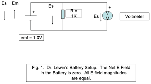
For example, in his battery setup (Fig. 1) Dr. Lewin assumes a net battery ##E## field opposite to the direction of the ##E## field in the resistor. Yet the battery has two canceling ##E## fields. ##E_s## points + to – and ##E_m## points – to +. The line integral of ##E_m## over the length of the battery (- to +) is the emf of the battery. A voltmeter senses the line integral of ##E_s## only, otherwise the meter would read 0V DC. The resistor has an ##E_s## field pointing + to -; the circulation of ##E_s## around the loop is zero as required by Kirchhoff’s voltage law. The circulation of ##E_m##, and thus ##E##, is ##iR##, ##i## being the current and ##R## the resistor.*
Now to address the main topic here, that of the solenoid, the single-turn loop, and voltmeters positioned as shown in Fig. 2. In what follows, loop resistance is again assumed zero.

Let
##\phi## = magnetic flux inside loop,
loop radius =##a##
loop current = ##i##
total loop induced emf = ## \oint \bf E_m \cdot \bf dl ##
then $$ E_m = \frac {\frac {-d\phi} {dt}} {2\pi a} $$.
Around the loop with or without the two resistors ##R1## and ##R2## in it, a continuum of ##E_m## field exists throughout the loop, with an ##E_s## field running in the opposite direction.
In the resistors ##E_s## can be very large as ## E_s = iR/d ## with d the length of each resistor, ##d \ll {2\pi a} ##. All of this follows immediately from the realization that ##\oint \vec E_s \cdot d \vec l = 0## and the line integral of the two resistors’ ##E_s## fields = ##\mathcal E##, being canceled around the loop by the wire segments’ ##E_s## fields.
Let us next show that a voltmeter as arranged in Fig. 3 and connected at two points a and b along the loop not including a resistor, reads 0V. That this crucial fact is perhaps paradoxical but entirely logical can be shown as follows:
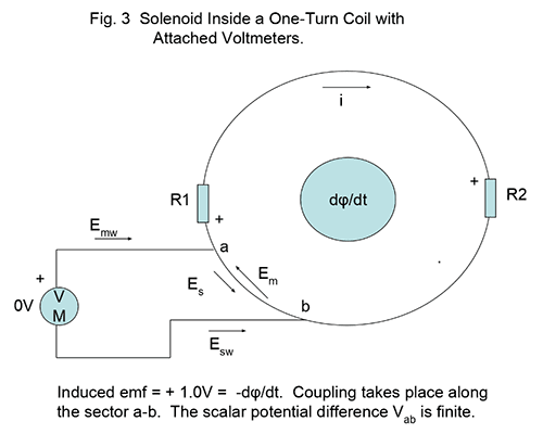
First, we remind ourselves that ##E_s## and ##E_m## are always equal and opposite in the wire including the shorter section a-b, as well as in the meter leads since a perfect conductor cannot have a net E field. This is a crucial assumption.
Let
##E_{mw}## = the static field in the meter leads ,
##E_{sw}## = the emf field in the meter leads,
##E_{sv}## = the static field in the voltmeter,
##E_{mv}## =the emf field int he voltmeter,
##l_w## = the total meter lead length,
We model the voltmeter as a resistor ##r## of finite physical length ##d##, of arbitrarily high resistance ##r## and passing correspondingly low current ##i_v## with the voltmeter reading ## i_v \cdot r####.
We must then also take cognizance of the fact that, for the voltmeter, ##i_v \cdot r = (E_{sv} – E_{mv}) \cdot d ## since ##E_{sv} ## and ##E_{mv} ## oppose. Thus, ##d \cdot E_{sv} = i \cdot r + d \cdot E_{mv} ##.
With this in mind, performing the circulation of ##E_s## around the meter circuit,
## +E_{sw} \cdot l_w + i_v \cdot r + E_{mv} \cdot d ~ – ~ E_s\theta a = 0 ##
The circulation of ##E_m## is also zero since there are no sources of emf within or around that contour:
## E_{mw} \cdot l_w + d \cdot E_{mv} – E_m \theta a = 0 ##
Combining these last two, with ##E_{sw} = E_{mw} ## and ##E_s = E_m ## as required,
##i_v\cdot r = 0, i_v = 0, VM = 0 ##.
Since VM = 0 for an uninterrupted section of the loop, it follows that the voltage read by a voltmeter probing a length of wire with a resistor ##R## in-between, VM = ##iR## and is not dependent on the length of wire segments surrounding ##R##. This argument includes of course Lewin’s famous A and D points which are located at the top and bottom respectively of the loop as in figs. 2 or 3.
We thus distinguish between VM readings and the so-called “scalar potential” difference which is here ##\int \bf E_s \cdot \bf dl.## McDonald rightly offers that meter wire coupling is accountable for the difference, which is why he argues for accepting scalar potential differences as the “true” potential difference, not subject to measurement detail. This is also the explanation offered by Mr. Mabilde. The latter demonstrated an apparently valid way of measuring the scalar potential experimentally with his interior voltage measuring setup, arriving at the correct scalar potential in all cases. However, his demo is simply a simulation of the Es field profile around the ring, set up by the area of his meter leads..
His statement criticizing Lewin’s “Kirchhoff was wrong” is however spot-on if we understand that the Kirchhoff voltage law applies to voltages in the correct sense of the word, which is the line integral of the Es field only and does not apply to Em fields.
I want to emphasize that the voltmeter readings in Lewin’s setup can be entirely accounted for without splitting the E field into Em and Es. What I think I contribute is more insight into the observed phenomena. I believe I have offered a precise explanation for the difference between meter readings and scalar potential differences. It’s not meter lead dress as suggested by Mr. Mabilde that matters; any meter loop in any orientation will give the same results. It’s simply ##E_m## and ##E_s## sharing between loops. As McDonald points out, if you want to avoid the consequences of loop coupling then the meter probes must be connected right at a resistor or the scalar potential difference reading will be wrong since those potentials associated with the loop wiring will not be included..
Lewin did not to my recollection place the VM leads in the middle of the solenoid. I think we can all accept that the reading would be half-way between -0.1V and + 0.9V, i.e +0.4V. Reflecting on the numerical mismatch between expected and actual VM readings, we see that the ##R1## meter reading was -0.1V – 0.4V = -0.5V i.e. too negative, while for the ##R2## loop it was +0.9V – 0.4V = +0.5V (too positive). Now, if we integrate the ##E_s## field over the meter loop with the meter positioned half-way, i.e. directly above, the solenoid, we can sum the line integral of ##E_s## as follows:
## \mathcal E##/2 – ##iR2## + VM = 0 or VM = +0.4V.
Or, –VM + ##\mathcal E##/2 –##iR1## = 0 also giving VM = +0.4V. Which agrees with the data. Suspending the voltmeter with its leads directly above the magnetic source gives the correct voltage.
To summarize, one should be aware of two separate electric fields in the loop and meter lead wiring vs. (essentially) one only in the resistors. Voltmeters give erroneous voltage readings if the meter circuit forms an alternative path for the Em field, as it does in the Lewin set up and readings. Coupling effects are predictable and can be shown to be ##E_m## and ##E_s## field sharing between the main loop and the meter loop. Spurious coupling must be identified and avoided if one wishes to obtain actual scalar potential differences; this may not always be an easy task.
Failure to recognize the two types of ##E## field is bound to lead to confusion or even violation of physics laws in any circuit containing one or more sources of emf, be they batteries, magnetic induction, or any other form of emf generation.
Cf. Stanford Professor Emeritus H. H. Skilling, Fundamentals of Electric Waves, probably out of print but readily available on the Web.
References:
- https://www.youtube.com/watch?v=FUUMCT7FjaI
- https://www.physicsforums.com/threads/faradays-law-circular-loop-with-a-triangle.926206/page-4
- Attachment: K. McDonald: “Lewin’s Circuit Paradox”
- Attachment: K. McDonald, “What Does a Voltmeter Measure?”
AB Engineering and Applied Physics
MSEE
Aerospace electronics career
Used to hike; classical music, esp. contemporary; Agatha Christie mysteries.


BTW Contrary to the statement in the above cited Insight article, of course there are both electric and magnetic fields in stationary circuits (in fact there's only one electromagnetic field in nature, but that's another story)..E[SUB]m[/SUB] is also an electric, not a magnetic field. Two E fields: E[SUB]s[/SUB] and E[SUB]m[/SUB]. One begins and ends on charges; the other does not.
@vanhees71 makes a very good point, you can no longer use the term "voltage" when you include a circuit loop that has a changing magnetic field inside of it. ## \ ## The "voltmeter" does not measure a "voltage" difference in this case, between the two points on the circuit that it probes.## \ ## Instead, the voltmeter needs to be considered for what it actually is=a couple of wires with a large resistor through which a small current flows. In this case, the voltmeter really doesn't "measure". Instead, it gives a reading which is the (multiplicative) product of the small current times the large resistor. The placement of the wires that form the leads of the voltmeter can yield different results depending on whether the circuit loop that they form encloses the changing magnetic field, in which case there is an EMF around that circuit loop.Yes. Your resistive voltmeter shows the field equivalent of Ohm's law which is ir = d(E[SUB]s[/SUB] + E[SUB]m[/SUB]) with d the length of r. This reduces to ir = dE[SUB]s[/SUB] if d << voltmeter wire lead lengths. In my various posts I had made this assumption.
There is no paradox whatsoever!. I admit, it took me a while to understand what is going on.
First thing first, the loop with two resistor is a red hearing. So, let's remove it and we get a circuit like that:
View attachment 237904
Now, we have a loop containing two voltmeters encircling flux change of 1 Wb/s. Obviously, the induced EMF is 1 Volt and the direction is indicated by the circular arrow. With the way the voltmeters are connected, the one on the right would show a positive voltage, the other negative voltage, just like in the video.
How much will each of them show?. That would depend on the internal resistance of the voltmeters. Portable meters have resistance of 10 Mohm, if both have this value, one will show 0.5 V, the other -0.5 V. Change the internal resistance of the left voltmeter to 1 Mohm and the other one to 9 Mohm and you will get -0.1 v and 0.9 V. No paradox, just a red herring.
However, Dr Lewin makes a statement in his video that I would disagree. He says that the Kirchhoff (second) law is not valid. The way I was thought physics, it is still valid. I understand that the Kirchhoff law says that for a loop ##sum I_k R_k = sum EMF## and that actually agrees with the Faraday law.
Now, I would also like to point out that the supposed tutorial contains some false statements. One of the false statement is
"which is non-conservative in the sense that its circulation is non-zero. E[SUB]m[/SUB] can be created by a chemical battery, magnetic induction, the Seebeck effect, and others."
This statement is not correct. The non-conservative electric field can only be created by changing magnetic flux. The field inside a battery is conservative. How is it created.
The key to understand operation of a battery is thermodynamics and equilibrium condition for particle exchange. Thermodynamics tells us that a system is at equilibrium with a reservoir with respect to particle exchange if the chemical potentials are equal. Let's take, for example, an alkaline battery. It consist of a zinc cathode, MnO anode and KOH electrolyte. KOH in solution dissociates into K[SUP]+[/SUP] and OH[SUP]-[/SUP] ions. At the cathode, the following reaction takes place ( see https://en.wikipedia.org/wiki/Alkaline_battery )
Zn(s) + 2OH[SUP]−[/SUP][SUB](aq)[/SUB] → ZnO(s) + H[SUB]2[/SUB]O + 2e[SUP]−[/SUP]
The reaction of solid Zn with OH[SUP]-[/SUP] ions produces ZnO, water and free electrons. Where do the free electrons go? they go to the Zn metal charging it up negatively, i.e. increasing the chemical potential of electrons in the metal. The reaction stops when the chemical potential of electrons in the Zn metal become equal to the chemical potential of the electrons attached to OH[SUP]-[/SUP] ions. The net result is formation of a potential difference at the electrode/electrolyte interface. This is not unlike creation of the depletion layer in a p-n junction of a semiconductor.
Similarly, there is a potential step created at the anode. The total voltage of an (open circuit) battery is algebraic sum of the two voltage steps.
Seebeck effect, photovoltaic cell EMF can also be understood considering the thermodynamics, that is, EMF is created by a gradient of chemical potential of electrons and the field is conservative.
Another equivalent view is that the EMF drives the electrons in the wires making up the volt meter (think of an old-fashioned galvanometer for simplicity), leading to the current @Charles Link mentioned in the previous posting.
This becomes clear if one uses the complete (!) integral form of Faraday's Law of induction. Its fundamental form is, as anything in electromagnetism, the local form in terms of derivatives (SI units):
$$-partial_t vec{B}=mathrm{nabla} times vec{E}.$$
Now if you integrate this over an arbitrarily moving area ##A## with boundary ##partial A## you can first use Stokes's theorem. The only correct version of this simple treatment is
$$-int_{A} mathrm{d}^2 vec{f} cdot partial_t vec{B} = int_{partial A} mathrm{d} vec{r} cdot vec{E}.$$
Now one likes to express in terms of the magnetic flux through the area
$$Phi_{vec{B}}=int_A mathrm{d}^2 vec{f} cdot vec{B}.$$
Now, if the area and its boundary are moving, you cannot take the partial time derivative out of the integral in the previous equation but you get an additional line integral along the boundary curve of the surface, which you can lump to the integral on the right-hand side. Taking Gauß's Law for the magnetic field, ##vec{nabla} cdot vec{B}=0## into account the resulting equation gets
$$-dot Phi_{vec{B}} = int_{partial A} mathrm{d} vec{r} cdot (vec{E}+vec{v} times vec{B})=:text{EMF},$$
where ##vec{v}## is the velocity field along the moving boundary of the area we've integrated over.
Now if you choose the area such that its boundary is along the wires connecting the volt meter with the rest of the circuit, what it measures is in fact the electromotive force, i.e., the line integral along the closed (!) boundary. It's obviously the line integral over the force on a unit charge ##vec{E}+vec{v} times vec{B}##, and this shows that indeed that's the physical picture on what's measured given above: The force on the charges inside the wires connecting the volt meter with the rest of the circuit (including the wires making up the coil in the volt meter, if you take the model of a old-fashioned galvanometer setup).
This considerations also explain why the reading of the volt meter is beyond the simple Kirchhoff circuit theory: It's reading cannot be understood without taking into account the correct geometry of the connection of the volt meter with the rest of the circuit since this you need to calculate the line integral defining the EMF, which is what the volt meter measures. The Kirchhoff theory becomes applicable only if you make the wires connecting the volt meter very short, so that the magnetic flux through the corresponding current loop becomes negligibly small. Then the reading is what you expect according to the Kirchhoff circuit theory, i.e., the EMF through the element of the circuit you want to measure (which may be an Ohmic resistor, a capacitor, or coil).
Note: Another source of confusion is the very name "EMF" for the line integral: Here force is obviously not the modern notion of "force" (which is represented by the Lorentz force per unit charge, ##vec{E}+vec{v} times vec{B}##) but its meaning is more in the sense of "energy". Indeed the EMF is a line integral of the force along a closed loop. The very fact that the quantity is a line integral along a closed loop shows that it is NOT a "voltage". If there'd be a potential for the force integrated over, the integral over any closed loop is 0 (modulo the caveat that the region under consideration is simply connected!).
@vanhees71 makes a very good point, you can no longer use the term "voltage" when you include a circuit loop that has a changing magnetic field inside of it. ## \ ## The "voltmeter" does not measure a "voltage" difference in this case, between the two points on the circuit that it probes.## \ ## Instead, the voltmeter needs to be considered for what it actually is=a couple of wires with a large resistor through which a small current flows. In this case, the voltmeter really doesn't "measure". Instead, it gives a reading which is the (multiplicative) product of the small current times the large resistor. The placement of the wires that form the leads of the voltmeter can yield different results depending on whether the circuit loop that they form encloses the changing magnetic field, in which case there is an EMF around that circuit loop.
Well, there's nothing to fight about. I think there's no paradox at all (I don't like the word "paradox"; it just indicates a lack of careful analysis based on "common knowledge", which is contrary to the very basic principles of basic science). Just use Maxwell's equations, and everything is fine. Also avoid to talk about "voltage" as soon as emf's from time-varying magnetic fields are involved. BTW Contrary to the statement in the above cited Insight article, of course there are both electric and magnetic fields in stationary circuits (in fact there's only one electromagnetic field in nature, but that's another story). The only thing is that one can eliminate them from the considerations using the stated assumptions and lump everything in currents, voltages and emf's. That's because Kirchhoff's laws are nothing else than the integrated version of Maxwell's equations under the simplifying assumptions made.
Pace nobiscum. :cool:
I remember that thread. It got really heated among several people who really know their stuff. You may be right that it's semantics.
I really don't care enough about Professor Lewin to go down that rabbit hole, so I'm going to exit this conversation.
@anorlunda and @rude man I think you both may be arguing the very same thing, and it is open to debate whether the EMF generated in a loop by a changing magnetic field is part of Kirchhoff's voltage laws (KVL), or if it happens to be an exception that Professor Walter Lewin has highlighted. Others have previously argued this fine detail: See https://www.physicsforums.com/threa…ge-across-inductor.880100/page-5#post-5533643 . ## \ ## Right around post 83 @Dale and @vanhees71 went back and forth on this a couple of times, but I think everyone is in agreement on how this problem gets solved, and it is very useful that Professor Walter Lewin has pointed out this special case, even if he says a couple of things that perhaps also aren't 100% accurate.