Programming an ATmega8A using Arduino
If you are interested in programming and electronics, you probably do not need an introduction to Arduino. If you want to make your Arduino projects permanent, then it is a good idea to use solo microcontrollers rather than Arduino boards in the final setup. While Arduino boards are great for prototyping, buying an Arduino board for each and every project may not be very budget-friendly. Single microcontrollers often cost less than a full Arduino board. In some cases, one may need more than one microcontroller for their project, and in that situation, using two Arduino boards may not be the best solution. The ability to program microcontrollers with Arduino will allow users to write source code in C and then simply upload it to the MCU.
In this article, I will show you how to program an ATmega8A microcontroller using Arduino. I will assume that you have some basic experience in Arduino. Without further ado, let’s get started.
Table of Contents
Hardware Requirements
- An Arduino board (boards with ATmel AVR microcontrollers, like Uno, Mega, etc.; ##3.3~\mathrm{V}## boards like Due or Zero are not preferred) with a USB cable,
- ATmega8A microcontroller,
- A breadboard,
- Two ##22~\mathrm{pF}## capacitors,
- One ##100~\mathrm{nF}## capacitor,
- One ##2.2~\mathrm{\mu F}## capacitor,
- One ##16~\mathrm{MHz}## or ##11.0592~\mathrm{MHz}## crystal,
- One ##10~\mathrm{k\Omega}## resistor,
- One ##330~\Omega## resistor,
- One/two LEDs,
- Jumper wires.
Terminology and version
I should briefly mention the terminology we will be using. You have an Arduino board (Uno, Mega, etc.) which itself has a microcontroller (“MCU” in short). For example, the Uno board has an ATmega328P, while the Mega 2560 board has the ATmega2560. This MCU will be called the “on-board microcontroller” to distinguish it from the ATmega8A.
We will be referring to four types of pins in this article:
- The pins on the Arduino board. You use these pin numbers directly in the Arduino sketch, like digital pin 13 or analog pin A2.
- The pins of the onboard microcontroller. These are connected to the various pins on the Arduino board, but the mapping differs from one Arduino board to another. So, when necessary, we may directly refer to/access some pins of the onboard MCU rather than the corresponding pins on the Arduino board.
- The native pins/ports of the ATmega8A. These are named PCx, PDx, PBx, and so on. For details, refer to the pinout diagram in the ATmega8A datasheet.
- The Arduino pins of the ATmega8A. These are the pin numbers you will be using in your sketch that will be uploaded to the ATmega8A. There is a nice pinout diagram that shows which native pin of the ATmega8A corresponds to which Arduino pin number; we will come to it later.
Lastly, all sketches and steps in this article have been written w.r.t. Arduino IDE v1.8.13. These steps may change with major revisions in the IDE, and I will try to keep the article up to date as far as possible.
Preparing the Arduino board
- Plug the Arduino into your computer via the USB cable, and make sure the Arduino IDE can detect it (go to Tools ##\rightarrow## Get Board info; if nothing is shown, the IDE tells you to select a port, and the Ports menu is greyed out, your Arduino has not been detected by your computer).
- Open the
ArduinoISPsketch: Go to File ##\rightarrow## Examples ##\rightarrow## ArduinoISP ##\rightarrow## ArduinoISP. - Make sure the board definition in the IDE is set as per your Arduino board (Tools ##\rightarrow## Board) and the programmer is set to
AVRISP mkII(Tools ##\rightarrow## Programmer). - Upload the
ArduinoISPsketch to your Arduino.
Installing the board definition for ATmega8A
We shall use the MiniCore board definition by MCUdude. In this article, we are using v2.1.3, which is the latest at the time of writing. To install the board, please follow the steps in the GitHub page.
Setting up the circuit
At this juncture, you should first study the pinout diagram near the bottom of the README.md of the MiniCore GitHub repo. The pinout diagram shows which native pin of the ATmega8A corresponds to which Arduino pin. When writing your source code for the ATmega8A, you will use these Arduino pin numbers to refer to the pins. The pinout diagram will also help you in wiring the hardware later.
In order to program the ATmega8A, we shall be connecting the MOSI (Master Out – Slave In), MISO (Master In – Slave Out), and SCK (Serial Clock) pins on the ATmega8A to the corresponding pins of the onboard MCU. These pins will allow the onboard MCU to communicate with the ATmega8A.
As we have stated earlier, the mapping from the pins of the onboard MCU to the pins on the Arduino board differs from one board to another. Hence, we shall be using the ICSP header pins on the Arduino board, the pinout of which will be universal and invariant across Arduino boards. Note that boards like Uno and Mega (which have a separate chip for USB communication) have two sets of ICSP headers. We will use the headers for the main microcontroller, and these generally have the label “ICSP” beside them.
The headers have the following pinout:
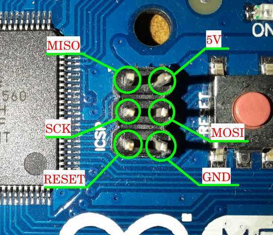
The pinout of the ICSP headers is also shown in the ArduinoISP sketch in the comments.
The full circuit, connecting the Arduino to the ATmega8A, is shown in the following diagram:
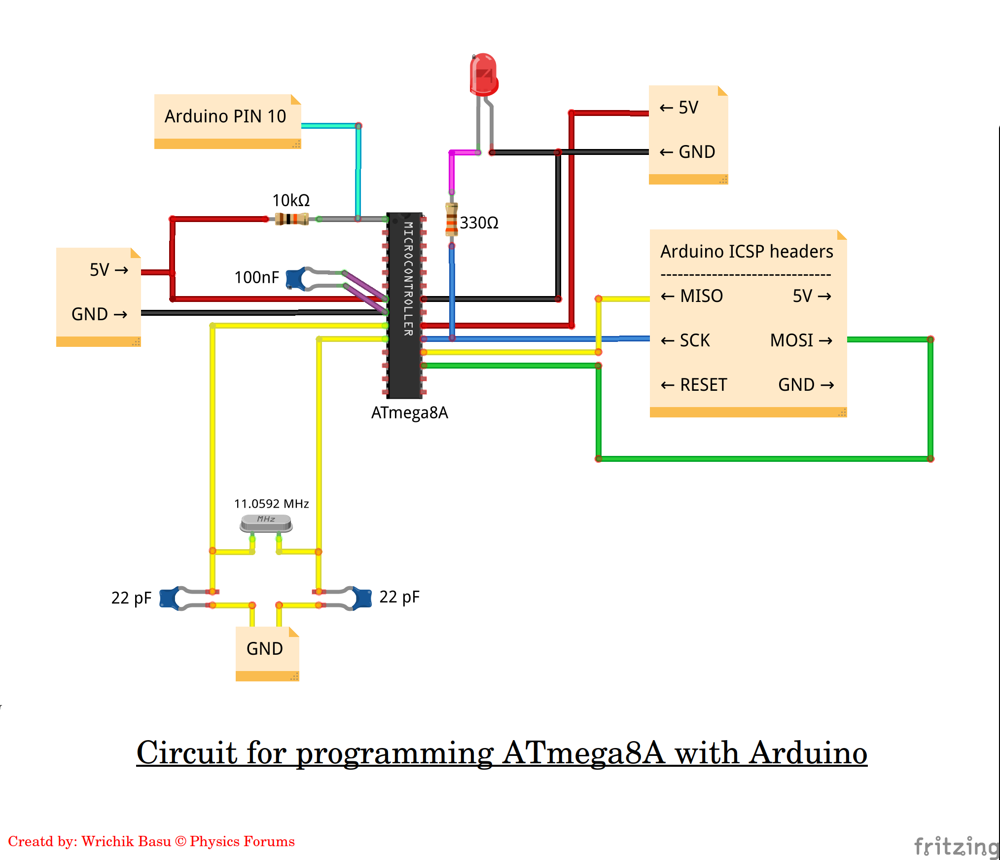
A few points to note:
- We do not use the ##\mathtt{RESET}## pin of the ICSP header. We have connected the ##\overline{\mathtt{RESET}}## (pin PC6) of the ATmega8A to pin 10 of the Arduino board and not to the ICSP header. The ##\mathtt{RESET}## pin of the ICSP header corresponds to the ##\overline{\mathtt{RESET}}## of the on-board MCU. Resetting the ATmega8A and the onboard MCU are two different stories and are not related to each other. We should be able to reset the ATmega8A independently when we are programming it. To this effect, the
ArduinoISPsketch, by default, uses the digital pin 10 on the Arduino board. Hence, irrespective of the board you are using, the ##\overline{\mathtt{RESET}}## of the ATmega8A will always be connected to digital pin 10 on the Arduino board. You may change this pin as per your wish by modifying theArduinoISPsketch. - I have used an ##11.0592~\mathrm{MHz}## crystal. You can choose any crystal from this list.
- While burning the bootloader or uploading a sketch, you have to compulsorily power the ATmega8A from the Arduino board. You may use the
5VandGNDpins on the ICSP header, or directly connect to the5VandGNDsockets on the Arduino board. If you are prototyping on a breadboard, then you may connect the power rails to the Arduino board.
Burning the bootloader
Once you have set up the circuit, as shown above, you are ready to burn the bootloader.
- First, you have to choose the correct board definition. In the Arduino IDE, go to Tools ##\rightarrow## Boards ##\rightarrow## MiniCore ##\rightarrow## ATmega8.
- Set the programmer to
Arduino as ISP (MiniCore)[Tools ##\rightarrow## Programmer ##\rightarrow## Arduino as ISP (MiniCore)]. - Choose the clock (crystal) you have used (Tools ##\rightarrow## Clock ##\rightarrow## …).
- The other options may be as follows:
- BOD: ##2.7~\mathrm{V}, ##
- EEPROM: EEPROM retained,
- Compiler LTO: LTO enabled
- Bootloader: Yes (UART0).
- Go to File ##\rightarrow## Preferences ##\rightarrow## Settings tab ##\rightarrow## “Show verbose output during…” and select both “Compilation” and “Upload” checkboxes. This will help you troubleshoot any errors that may arise.
- Click on Tools ##\rightarrow## Burn bootloader.
If everything goes well, there should be a message in the IDE: “Done burning bootloader“; if there are errors, scroll through the article to the “Dealing with runtime errors” section. If you have connected the LED to the SCK line of the ATmega8A as shown in the circuit diagram, it should start blinking after this if the burn succeeds.
Uploading sketches to the ATmega8A
To upload any sketch,
- Make sure you have chosen the correct board definition. The bottom-right corner of the IDE should show you the chosen board options.
- Compile the sketch.
- On the Arduino board, connect a ##2.2~\mathrm{\mu F}## capacitor between the
RESETandGNDpins. This will make sure that the on-board MCU stays reset during the upload process. (If you are using the Uno board, you may detach the on-board microcontroller by removing it from its IC base.) - The circuit will be the same as it was when you had burnt the bootloader.
- Go to Sketch ##\rightarrow## Upload using Programmer.
Test with a Blink sketch
Now you are ready to upload sketches to the ATmega8A. We shall test with the following Blink sketch, which is akin to the “HelloWorld” program.
void setup() {
    pinMode(17, OUTPUT);
}

void loop() {
    digitalWrite(17, HIGH);
    delay(1000);
    digitalWrite(17, LOW);
    delay(1000);
}
Note that digital pin no. 17 of the ATmega8A corresponds to port PC3. You should be able to locate this pin on the pinout diagram given in the MiniCore repo.
Connect a LED with a resistor between digital pin 17 of the ATmega8A and GND, and upload the sketch. If everything goes fine, the LED should start blinking. If you disconnect and reconnect power to the ATmega8A, the LED should start blinking again. Congratulations! You have successfully uploaded your first sketch to the ATmega8A.
Compatible microcontrollers
Although we have used the ATmega8A in this article to demonstrate the procedure, you can program many other microcontrollers in a similar fashion. MCUdude has written many other board definitions like MicroCore, MajorCore, MightyCore, and so on. The list of supported microcontrollers is given in the GitHub repos. For instance, MiniCore supports not only the ATmega8A, but also ATmega48, ATmega88, ATmega168, ATmega328, and ATmega328PB, and these can be programmed similarly. For other microcontrollers, make sure you study the pinout and minimal setup diagrams and modify the circuit accordingly.
Some points to keep in mind
- Once a sketch is uploaded, you may disconnect all pins from the Arduino board. You may provide the power source to the microcontroller externally without using an Arduino (like a 9V battery with a LM7805 voltage regulator, or directly from the mains AC using an AC-DC adapter).
- Not all Arduino libraries have been implemented in other microcontrollers. When you compile your sketch, you will get errors if the library you are using is not implemented.
- Microcontrollers have varying sizes of flash memory. If your sketch requires more memory than is available, the compiler will throw an error. Note that the bootloader uses 513 bytes of flash memory.
- You may use an internal clock and thereby gain two extra pins. But unless necessary, it is preferable to use an external clock.
- By default, LTO is disabled in the MiniCore board definition. This has been done to maintain backward compatibility with previous versions of the IDE. It is recommended to enable LTO, which can shrink your code and reduce its size at the time of linking. In some board definitions by MCUdude, LTO is enabled by default. Note that if you want to change the LTO option, it is not necessary to burn the bootloader again. You may simply change the option and compile your code again.
- It is not necessary to burn the bootloader every time you wish to upload a sketch. It is, however, necessary to burn the bootloader again in case you want to change any of the following options:
- BOD
- Clock frequency
- EEPROM option
Dealing with runtime errors
There are two types of errors that you may frequently encounter while uploading a sketch or burning the bootloader:
- Device signature invalid, and
- Timeout after no response from the microcontroller.
The most common reason for these errors is connections. Check if you have a loose connection somewhere, and verify that you have set up the circuit properly. Check connections for continuity with a multimeter. Sometimes, the IC may not have been firmly attached to the breadboard, so check that too. While uploading a sketch, make sure you connect the capacitor between RESET and GND in the Arduino board.
That’s all for this article. Thank you for reading through it, and I hope you will find it helpful.
I would like to take this opportunity to thank Greg Bernhardt, the creator, and admin of Physics Forums, for constantly motivating us to write articles in the Insights Blog and providing us with a platform where we can share our knowledge. I also thank the Mentors of Physics Forums for their dedication and hard work (which is completely voluntary), without which the website could not have become what it is today.
Questions, comments, and suggestions are always welcome.

Studying physics at a college in Kolkata, India. Interested in accelerator physics, beam instrumentation and diagnostics, and particle physics detector design. Also passionate in electronics and programming in Java, Android, MATLAB and Python.


@Borek
The MiniCore board definition allows one to use an internal clock. I had tried that initially, but I was getting device timeout error while burning bootloader or uploading code. It worked properly after I switched to a 16 MHz or 11.0592 MHz external crystal, and I have always used an external crystal thereafter.
Regarding generating the clock signal from the ATmega itself, I think I had read that somewhere, but can’t find it at the moment.
I think you actually don’t need crystal.
1. If memory serves me well It is possible to program the chip clocking it from an external signal supplied by the same ATmega you use for programming. It requires a bit of tinkering with the ArduinoISP code.
2. After programming you can use an internal oscillator. It is not as accurate (in terms of frequency) as the external quartz crystal, but as long as you don’t need too precise timing it gets the job done.