Draw out the circuit diagram for the following 2 output circuit

In summary, the Verilog module provided contains two output circuits: f and g. The inputs are x, y, and z. The circuit for f is composed of an AND gate with inputs x and y, and an inverter gate with input z, all connected to an OR gate. The circuit for g is composed of an OR gate with inputs f and an AND gate with inputs ~y and ~x, connected to an inverter gate. Careful attention must be paid to syntax and typos when designing circuits in Verilog.
  • #1
shamieh
539
0
Draw out the circuit diagram for the following 2 output circuit specified in the following Verilog module (AND - &, Or - |, Not - ~). Use AND, OR and Inverter Gates.

Module test1(f,g,x,y,z);
input x,y,z;
output f,g;

assign g = f(~y&~x);
assign f = x&y | ~x&z;
endmodule;

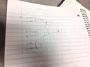
Here is my solution:

View attachment 1449
 

Attachments

  • photo(2).JPG
    photo(2).JPG
    25.6 KB · Views: 60
Technology news on Phys.org
  • #2
shamieh said:
Module test1(f,g,x,y,z);
input x,y,z;
output f,g;

assign g = f(~y&~x);
assign f = x&y | ~x&z;
endmodule;
I am not familiar with Verilog (I am using another software that uses file extension .v :)), but I don't understand "f(~y&~x)". Since there is no operator between f and (~y&~x), it looks like a function application, but f has not been declared a function (this requires the "function" keyword). I tried to compile this code on www.compileonline.com, and it seems to say the same thing:
Code:
main.v:5: error: No function f in this context (test1).
main.v:5: error: Unable to elaborate r-value: f((~(y))&(~(x)))

Besides, "module" in Verilog is written with a lowercase m and apparently there should not be a semicolon after "endmodule". If you want to design circuits, you have to be extra careful about such things.
 
  • #3
the f in f(~y&~x) means like the function f. So it's essentially saying that the function g = f (f = x&y | ~x&z;) OR (~y&~x); see what I'm saying?

and the endmodule should have been lower case. Mistake on my part.
 
  • #4
Evgeny.Makarov said:
I am not familiar with Verilog (I am using another software that uses file extension .v :)), but I don't understand "f(~y&~x)". Since there is no operator between f and (~y&~x), it looks like a function application, but f has not been declared a function (this requires the "function" keyword). I tried to compile this code on www.compileonline.com, and it seems to say the same thing:
Code:
main.v:5: error: No function f in this context (test1).
main.v:5: error: Unable to elaborate r-value: f((~(y))&(~(x)))

Besides, "module" in Verilog is written with a lowercase m and apparently there should not be a semicolon after "endmodule". If you want to design circuits, you have to be extra careful about such things.

I got mine to compile fine. It was a typo on my part originally i put a semicolon at the end which was wrong, but if you copy and paste this in the compiler you just linked me, it compiles and executes fine. But how do I actually draw this monster?:eek: Here is the code that will compile below if you want to try for yourself.
Code:
module test1(f,g,x,y,z);
    input x,y,z;
    output f,g;
    
    assign g = f|(~y&~x);
    assign f = x&y|~x&z;
endmodule
 
  • #5
shamieh said:
Code:
module test1(f,g,x,y,z);
    input x,y,z;
    output f,g;
    
    assign g = f|(~y&~x);
    assign f = x&y|~x&z;
endmodule
This makes a big difference because now there is an OR after f. So f is not a function, but a regular variable. Before, even if f had been declared a function using the "function" keyword, it would have been unclear how f, which depends on two inputs x and y, can be applied to a single argument (~y&~x).

If you understand the order of evaluation, drawing a circuit is easy.

(1) x and y go to an AND
(2) x gets inverted and with z goes to an AND
(3) outputs of (1) and (2) go to an OR
(4) y and x get inverted and to to an AND
(5) outputs of (3) and (4) go to an OR.
 

Related to Draw out the circuit diagram for the following 2 output circuit

1. What is a circuit diagram?

A circuit diagram is a graphical representation of an electrical circuit that shows the components and connections between them. It is used to visualize how electricity flows through a circuit and to help design and troubleshoot circuits.

2. How do I draw a circuit diagram?

To draw a circuit diagram, you will need a pencil, ruler, and paper. Start by identifying all the components in the circuit and their connections. Use symbols to represent each component and draw lines to show how they are connected. Be sure to label each component and connection for clarity.

3. What are the two outputs in this circuit?

The two outputs in a circuit refer to the points where electricity leaves the circuit to power other components. In this particular circuit, it could be two different devices or components that are being powered by the circuit.

4. Why is it important to draw a circuit diagram?

A circuit diagram is important because it helps to visualize and understand how electricity flows through a circuit. It also helps in designing and troubleshooting circuits, as well as documenting and communicating circuit designs to others.

5. Can I use software to draw a circuit diagram?

Yes, there are several software programs available that allow you to draw circuit diagrams. These programs often have features such as a library of pre-made symbols, automatic connections, and the ability to simulate the circuit. Some popular software options include AutoCAD, CircuitMaker, and Fritzing.

Similar threads

  • Programming and Computer Science
Replies
1
Views
2K
  • Programming and Computer Science
Replies
1
Views
2K
  • Programming and Computer Science
Replies
4
Views
3K
  • Programming and Computer Science
Replies
6
Views
2K
  • Introductory Physics Homework Help
Replies
9
Views
1K
  • Programming and Computer Science
2
Replies
59
Views
9K
  • Engineering and Comp Sci Homework Help
Replies
31
Views
3K
  • Programming and Computer Science
Replies
8
Views
3K
  • Programming and Computer Science
Replies
23
Views
2K
  • Calculus and Beyond Homework Help
Replies
8
Views
761
Back
Top