Exit velocity through a nozzle: Bernoulli vs. Experience

In summary: So in the end, the exit speed is still the same.When gardening with a hose for example. By pressing the nozzle to make it smaller the water exits significantly faster.It's true I don't know the conditions upstream but let's imagine the hose is being supplied by the same tank as described in #1.When gardening with a hose for example. By pressing the nozzle to make it smaller the water exits significantly faster.It's true I don't know the conditions upstream but let's imagine the hose is being supplied by the same tank as described in #1.
  • #1
Juanda
Gold Member
424
149
TL;DR Summary
Bernoulli equations result in exit speed being independent of the nozzle diameter which contradicts personal experiences. What am I missing?
There is a classical example when teaching Bernoulli equations to get the exit velocity of a fluid leaving through the bottom of a tank. If we consider no energy is lost due to friction, the exit velocity turns out to be ##v=\sqrt {2gh}##. I'm having trouble processing the fact that exit speed is independent of nozzle diameter because it contradicts my real-world experience.

Let's assume an ideal scenario where there are no losses in pressure due to friction, water is incompressible and the area of the tank is MUCH greater than the area of exiting pipe. Then, Bernoulli can be applied in the following form.

1687700850722.png

##P_1+\rho gh_1+\frac{1}{2}\rho v_1^2=P_2+\rho gh_2+\frac{1}{2}\rho v_2^2\rightarrow v_2=\sqrt {2gh_1}##

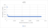
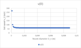
According to that, no matter the diameter of the nozzle (as long as ##A_1>>A_2## and the time interval considered is not too long) I will get the same exit speed. I would expect that as I reduce the nozzle diameter, the exit speed should increase. At least, that's what my real-world experience tells me.
Am I missing something?
Is this due to the idealization of the problem? If losses due to friction and the nozzle were considered would the diameter of the nozzle affect the exit speed?
 
Last edited:
Physics news on Phys.org
  • #2
Frabjous said:
What is your real world experience with this experiment?
When gardening with a hose for example. By pressing the nozzle to make it smaller the water exits significantly faster.
It's true I don't know the conditions upstream but let's imagine the hose is being supplied by the same tank as described in #1.
 
  • #3
Juanda said:
When gardening with a hose for example. By pressing the nozzle to make it smaller the water exits significantly faster.
It's true I don't know the conditions upstream but let's imagine the hose is being supplied by the same tank as described in #1.
This is a very, very different situation. The garden hose and house piping waste virtually all of the available pressure before the water gets to the exit. By blocking part of the hose you reduce the flow rate which reduces the loss. That's why when you do this the rise in velocity isn't instantaneous; you can actually feel and see the pressure building.
 
  • #4
Juanda said:
When gardening with a hose for example. By pressing the nozzle to make it smaller the water exits significantly faster.
It's true I don't know the conditions upstream but let's imagine the hose is being supplied by the same tank as described in #1.
This isn’t at all the same scenario as in the OP. The diameter of the nozzle is comparable to the diameter of the hose. And the flow velocity in the hose is substantial. Bernoulli’s does apply, but not the result derived from a different scenario.
 
  • #5
Juanda said:
View attachment 328358
P1+ρgh1+12ρv12=P2+ρgh2+12ρv22→v2=2gh1

Is this due to the idealization of the problem? If losses due to friction and the nozzle were considered would the diameter of the nozzle affect the exit speed?
The idealization is the issue. If you include losses ( and suppose h1 is being maintained ), for steady flow the first and second laws of thermodynamics applied result in "The Energy Equation". Its basically "Beroulli's" with some additional terms:

$$h_p+\frac{P_1}{\rho g}+h_1+\alpha_1\frac{V_1^2}{2g}=h_t+\frac{P_2}{\rho g}+h_2+\alpha_2\frac{V_2^2}{2g}+\sum_{1 \to 2}h_l$$

##h_p## is the head of the pump
##h_t## head of a turbine
##\alpha## is characterized by the flow regime ( Laminar - 2 , turbulent ≈1.05)
The last terms on the RHS are the (viscous) head losses and they are always positive by application of the Second Law.

$$ \sum_{1 \to 2} h_l = \sum_{1 \to 2} k_i \frac{V_i^2}{2g}$$

##k## can be a function of the geometry of the conduit in each section, as well as the flow regime.

So including that, you will find that if you start messing with the hose/nozzle geometry, you will indeed be changing the flowrate of the system.

This is the practical engineering approach anyhow.
 
Last edited:
  • #6
My Latex has seemed to inexplicably convert to regular text upon edit. I since fixed it. Is that something I did without realization?
 
Last edited:
  • #7
I caught a few mistakes after posting the reply. I think I corrected them at #8.

russ_watters said:
This is a very, very different situation. The garden hose and house piping waste virtually all of the available pressure before the water gets to the exit. By blocking part of the hose you reduce the flow rate which reduces the loss. That's why when you do this the rise in velocity isn't instantaneous; you can actually feel and see the pressure building.

I think I understand the concept of what you're saying. I consider it somewhat counterintuitive because it feels like by introducing more losses at the nozzle we reduce the speed of the flow. Since most of the losses are due to that speed, then the total losses are decreased and we get a greater exit speed.
NOTE AFTER SEEING THE MATH: Although it seemed counterintuitive, I understood it once I realized that even if you get a greater exit speed by blocking the nozzle, the flow is reduced so it doesn't feel like cheating anymore.

I'll try to express the problem with math to make sure I'm getting it.

Let's then assume a tank again as described in #1. However, now there will be a 100m long hose ##(L)## at the bottom with a 20mm in diameter ##(D_h)##and a nozzle at the end with a different diameter ##D_n##. The water at the tower will be 20m high ##(h_1)##. Fluid is water so I will use ##\rho = 1000 \frac{kg}{m^3}## for the density and for the viscosity ##\mu = 10^{-3} Pa·s##.
Losses at the hose will be ##P_{hose_{loss}}=f_D \frac{\rho Lv^2}{2D_h}##. For simplicity, let's assume laminar flow so ##f_D=\frac{64}{Re}##. Then, the pressure loss at the hose will be ##P_{hose_{loss}}=\frac{32L\mu v}{D_h^2} ##.
Losses at the nozzle will depend on its geometry. As a simplification, I assume it'll be ##P_{nozzle_{loss}}=k \frac{\mu v}{A_n}=k \frac{4 \mu v}{\pi D_n^2}## where ##k=1## and it's there simply to make the units right. That function is not based on experiments. It's just to have something that makes losses in pressure greater as speed increases and smaller as the area increases to have some similarity with the real world but keep the equations simple.

Finally, applying Bernoulli again but taking the losses into account I get:
##P_1+\rho gh_1+\frac{1}{2}\rho v_1^2=P_2+\rho gh_2+\frac{1}{2}\rho v_2^2\ + P_{hose_{loss}} +P_{nozzle_{loss}}##
##{\left \{ P_1=P_2=P_{atm};\ A_1>>A_2 \rightarrow v_1 \approx 0; h_2=0 \right \}}##
##\rho gh_1=\frac{1}{2}\rho v_2^2 + \frac{32L\mu v_2}{D_h^2} + k \frac{4 \mu v_2}{\pi D_n^2} \rightarrow ##
##{\color{Red}\rightarrow{\frac{1}{2}\rho v_2^2 +\left (\frac{32L \mu }{D_h^2} + k \frac{4 \mu }{\pi D_n^2}\right )v_2 - \rho gh_1=0} }##I can then find the exit velocity ##v_2## as a function of the nozzle diameter ##D_n##. Also, the flow will be given by ##\dot{V}=v_2 \frac{\pi D_n^2}{4}##
1687711848610.png


This time I do get the behavior I am used to from my "real-world experience". As the nozzle diameter decreases, the exit speed increases. As the diameter becomes big enough, the exit velocity is basically constant. For these numbers, it ends up at ~55 m/s because of the loss of pressure in the hose. Also, the flow is always increasing with the nozzle diameter.

If I set the hose length to 0 then the speed approaches ##v_2= \sqrt{2gh} = 62.62 m/s## as the diameter of the nozzle increases.
1687711920144.png
I think I finally got it. Is there anything I got wrong? Besides all the simplifications I did for the problem regarding the losses in pressure in the hose and in the nozzle.
 

Attachments

  • 1687710591844.png
    1687710591844.png
    3.9 KB · Views: 66
  • 1687710972100.png
    1687710972100.png
    3.9 KB · Views: 73
Last edited:
  • #8
Juanda said:
I think I understand the concept of what you're saying. I consider it somewhat counterintuitive because it feels like by introducing more losses at the nozzle we reduce the speed of the flow. Since most of the losses are due to that speed, then the total losses are decreased and we get a greater exit speed.
NOTE AFTER SEEING THE MATH: Although it seemed counterintuitive, I understood it once I realized that even if you get a greater exit speed by blocking the nozzle, the flow is reduced so it doesn't feel like cheating anymore.

I'll try to express the problem with math to make sure I'm getting it.

Let's then assume a tank again as described in #1. However, now there will be a 100m long hose ##(L)## at the bottom with a 20mm in diameter ##(D_h)##and a nozzle at the end with a different diameter ##D_n##. The water at the tower will be 20m high ##(h_1)##. Fluid is water so I will use ##\rho = 1000 \frac{kg}{m^3}## for the density and for the viscosity ##\mu = 10^{-3} Pa·s##.
Losses at the hose will be ##P_{hose_{loss}}=f_D \frac{\rho Lv^2}{2D_h}##. For simplicity, let's assume laminar flow so ##f_D=\frac{64}{Re}##. Then, the pressure loss at the hose will be ##P_{hose_{loss}}=\frac{32L\mu v}{D_h^2} ##.
Losses at the nozzle will depend on its geometry. As a simplification, I assume it'll be ##P_{nozzle_{loss}}=k \frac{\mu v}{A_n}=k \frac{4 \mu v}{\pi D_n^2}## where ##k=1## and it's there simply to make the units right. That function is not based on experiments. It's just to have something that makes losses in pressure greater as speed increases and smaller as the area increases to have some similarity with the real world but keep the equations simple.

Finally, applying Bernoulli again but taking the losses into account I get:
##P_1+\rho gh_1+\frac{1}{2}\rho v_1^2=P_2+\rho gh_2+\frac{1}{2}\rho v_2^2\ + P_{hose_{loss}} +P_{nozzle_{loss}}##
##{\left \{ P_1=P_2=P_{atm};\ A_1>>A_2 \rightarrow v_1 \approx 0; h_2=0 \right \}}##
##\rho gh_1=\frac{1}{2}\rho v_2^2 + \frac{32L\mu v_2}{D_h^2} + k \frac{4 \mu v_2}{\pi D_n^2} \rightarrow ##
##{\color{Red}\rightarrow{\frac{1}{2}\rho v_2^2 +\left (\frac{32L \mu }{D_h^2} + k \frac{4 \mu }{\pi D_n^2}\right )v_2 - \rho gh_1=0} }##I can then find the exit velocity ##v_2## as a function of the nozzle diameter ##D_n##. Also, the flow will be given by ##\dot{V}=v_2 \frac{\pi D_n^2}{4}##
View attachment 328366

This time I do get the behavior I am used to from my "real-world experience". As the nozzle diameter decreases, the exit speed increases. As the diameter becomes big enough, the exit velocity is basically constant. For these numbers, it ends up at ~55 m/s because of the loss of pressure in the hose. Also, the flow is always increasing with the nozzle diameter.

If I set the hose length to 0 then the speed approaches ##v_2= \sqrt{2gh} = 62.62 m/s## as the diameter of the nozzle increases.
View attachment 328368I think I finally got it. Is there anything I got wrong? Besides all the simplifications I did for the problem regarding the losses in pressure in the hose and in the nozzle.

I'm sorry but there are a few mistakes I found after replying.
  1. I didn't use the height for the tank and the length of the pipe I initially established.
  2. I missed a (-) when making the formulas in Excel.
  3. It is necessary to add a 3rd point to the diagram now that I added the hose.
The problem now looks like this.
1687716716852.png
Using Bernoilli between 1 and 3:
##P_1+\rho gh_1+\frac{1}{2}\rho v_1^2=P_3+\rho gh_3+\frac{1}{2}\rho v_3^2\ + P_{hose_{loss}} +P_{nozzle_{loss}}##

Pressure loss at the hose assuming laminar flow for simplicity:
##P_{hose_{loss}}=f_D \frac{\rho Lv_2^2}{2D_h} \left \{ f_D=\frac{64}{Re} \right \}\rightarrow P_{hose_{loss}}=\frac{32L\mu v_2}{D_h^2}##

Pressure loss at the nozzle according to the function (justification for the function is at #7):
##P_{nozzle_{loss}}=k \frac{\mu v_3}{A_n}=k \frac{4 \mu v_3}{\pi D_n^2}##
##k## is 1 and it's there just to make the units right.

Then, Bernoulli between 1 and 3 will be:
##\rho gh_1=\frac{1}{2}\rho v_3^2\ + \frac{32L\mu v_2}{D_h^2} + k \frac{4 \mu v_3}{\pi D_n^2}##

I need the previous equation in terms of ##v_3## so using mass continuity and incompressible flow:
##Q_2=Q_3 \rightarrow v_2A_2=v_3A_3 \rightarrow v_2 = v_3 \frac{D_n^2}{D_h^2}##

Plugging that into the Bernoulli equation results in:
##\rho gh_1=\frac{1}{2}\rho v_3^2\ + \frac{32L\mu v_3 \frac{D_n^2}{D_h^2}}{D_h^2} + k \frac{4 \mu v_3}{\pi D_n^2}##
##\rho gh_1=\frac{1}{2}\rho v_3^2\ + \frac{32L\mu v_3D_n^2}{D_h^4} + k \frac{4 \mu v_3}{\pi D_n^2}##

I can then plot the exit velocity ##v_3## and volumetric flow ##Q## as a function of ##D_n##.

Using the Internation system, for the values ##\rho = 1000; L=100; \mu=0.001; g=9.8; h_1=20; D_h=0.02## the result is:
1687718912792.png


It can be seen how reducing the nozzle diameter results in a greater exit speed but it lowers the flow rate.
 
Last edited:
  • Like
Likes erobz

FAQ: Exit velocity through a nozzle: Bernoulli vs. Experience

What is the principle behind Bernoulli's equation in determining exit velocity through a nozzle?

Bernoulli's equation is based on the principle of conservation of energy for a flowing fluid. It states that the sum of the kinetic energy, potential energy, and internal energy (pressure) per unit volume remains constant along a streamline. When applied to a nozzle, Bernoulli's equation helps calculate the exit velocity by considering the pressure difference and fluid density between the entrance and exit of the nozzle.

How does real-world experience differ from theoretical predictions using Bernoulli's equation?

In real-world applications, factors such as friction, turbulence, and non-ideal fluid behavior can cause deviations from the ideal predictions provided by Bernoulli's equation. These factors can lead to energy losses not accounted for in the theoretical model, resulting in an actual exit velocity that is often lower than the calculated value.

Can Bernoulli's equation be used for compressible fluids in nozzles?

Bernoulli's equation is primarily derived for incompressible fluids, where the fluid density remains constant. For compressible fluids, such as gases, the equation needs modifications to account for changes in density and the compressibility effects. In such cases, more complex models like the isentropic flow equations are used to predict exit velocity.

What role does nozzle design play in determining exit velocity?

Nozzle design significantly impacts the exit velocity. Factors such as the nozzle shape (convergent, divergent, or convergent-divergent), length, and surface roughness can influence the fluid flow characteristics. A well-designed nozzle minimizes energy losses and turbulence, optimizing the exit velocity and efficiency of the fluid flow.

How can experimental data be used to improve predictions of exit velocity through a nozzle?

Experimental data provides valuable insights into the actual performance of a nozzle under various conditions. By comparing experimental results with theoretical predictions, discrepancies can be identified and used to refine models. Empirical correlations and correction factors derived from experimental data help improve the accuracy of exit velocity predictions, accounting for real-world influences such as friction and turbulence.

Similar threads

Replies
5
Views
1K
Replies
20
Views
8K
Replies
12
Views
4K
Replies
2
Views
9K
Replies
33
Views
11K
Replies
6
Views
3K
Replies
18
Views
5K
Back
Top