How to Calculate Torque for a Rotating Rack?

In summary, the weight of the rack is supported by an axial bearing and the torque has been calculated by considering the chain traction force and required shaft power. The treatment of the moment of inertia and distribution of mass on the circular plates is still unknown. The turntable's mass moment of inertia needs to be computed to spec a motor, taking into account frictional losses in bearings and other drive components. The rack should be treated as point masses at their radius of rotation, while the plates, shaft, and gears should be treated as cylinders. The driver gear should also be taken into account and an acceptable angular acceleration needs to be determined for the application.
  • #1
Aaron Mac
26
1
Homework Statement
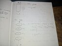
Smaller sprocket (15 TEETH) is attached to the shaft of the motor and larger sprocket (30 teeth) is attached to the shaft of the rack. I am targeting a speed of 10rpm to 12rpm of the rack. However, i am having trouble sizing the motor for this action.
Relevant Equations
Chain traction force, Shaft power
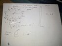
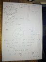
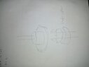
The weight of the rack is supported on an axial bearing as seen in the attached pdf below. I have made an attempt to calculate the torque by taking a look at the chain traction force and the required shaft power to make the plates rotate. For the moment of inertia case i don't know how to treat this case also and also mass will be distributed at random on the circular plates. Please can someone help me or guide me
 

Attachments

  • Screenshot (51).pdf
    319.3 KB · Views: 95
Last edited:
Physics news on Phys.org
  • #2
10 -12 rpm? Additional mass(s) placed at random places. Is this a rotating cupcake display?
 
  • Like
Likes scottdave and Aaron Mac
  • #3
Anyhow. To get started, in order to spec a motor you should compute the mass moment of inertia of the turntable. This is relevant for the period of time when the turntable is accelerating from rest to the desired rpm. After acceleration of the system has ceased, the remaining power demand will be frictional losses in bearings and other drive components. In general, you should be basically shooting for a slight overestimate.
 
Last edited:
  • Like
Likes Lnewqban and Aaron Mac
  • #4
erobz said:
10 -12 rpm? Additional mass(s) placed at random places. Is this a rotating cupcake display?
No haha but could use it!
 
  • #5
erobz said:
Anyhow. To get started, in order to spec a motor you should compute the moment of inertia of the turntable. this is relevant for the period of time when the turntable is accelerating from rest to the desired rpm. After acceleration of the system has ceased, the remaining power demand will be frictional losses in bearings and other drive components. In general, you should be basically shooting for a slight overestimate.
Yes but how do i treat the rack? As a solid cylinder? Or individual circular disks? That is 4 circular disks? And from there on what shall be calculated to find the torque required?

Have you seen the attached pdf above? Is it relevant?

Kind Regards,
Aaron
 

Attachments

  • d.jpg
    d.jpg
    30.8 KB · Views: 84
  • #6
Aaron Mac said:
Yes but how do i treat the rack? As a solid cylinder? Or individual circular disks? That is 4 circular disks? And from there on what shall be calculated to find the torque required?

Have you seen the attached pdf above? Is it relevant?

Kind Regards,
Aaron
Treat the vertical posts as point masses at their radius of rotation. The plates as cylinders of radius ##r_{p}##, shaft as a cylinder, gears as a cylinder. Treat each of the randomly placed masses at the furthest radial distance possible (maintaining symmetry - unbalanced thigs tend to wobble) as point masses. That should maximize the moment of inertial, giving you some built in "fudge factor"
 
Last edited:
  • Like
Likes Lnewqban and Aaron Mac
  • #7
erobz said:
Treat the vertical posts as point masses at their radius of rotation. The plates as cylinders of radius ##r_{p}##, shaft as a cylinder, gears as a cylinder. Treat each of the randomly placed masses at the furthest radial distance possible (maintaining symmetry - unbalanced thigs tend to wobble) as point masses. That should maximize the moment of inertial, giving you some built in "fudge factor"
Thank you for your answer once again. I have attached an image below for the derivation, sorry for the uncleanliness btw. Should i also take into account the driver Gear also?

Let's suppose i get Total Moment of inertia as 100kgm^2. What do i do next?

Thank you for your guide dear friend!
 

Attachments

  • 2e.jpg
    2e.jpg
    23.1 KB · Views: 79
  • #8
Aaron Mac said:
Should i also take into account the driver Gear also
Yes, just start at the pinion and work your way out from there.

Note, be careful with the gears (they have related but different angular velocities). You are going to have to relate them to the angular acceleration of the table when accounting for their moment of inertia.
Aaron Mac said:
Let's suppose i get Total Moment of inertia as 100kgm^2. What do i do next?
After that you need to determine an acceptable angular acceleration for the application. Just pretend you want the angular acceleration to be constant ( I won't be in reality, but we are just aiming for an upper bound at the moment)... This thing is rotating fairly slowly. Maybe you can accept this turntable taking 2 full rotations to get up to full speed, maybe 4 ? from there what kinematic relationship would you apply to determine ##\alpha##, that involves ##\omega, \theta##?
 
Last edited:
  • #9
erobz said:
Yes, just start at the pinion and work your way out from there.

Note, be careful with the gears (they have related but different angular velocities). You are going to have to relate them to the angular acceleration of the table when accounting for their moment of inertia.

After that you need to determine an acceptable angular acceleration for the application. Just pretend you want the angular acceleration to be constant ( I won't be in reality, but we are just aiming for an upper bound at the moment)... This thing is rotating fairly slowly. Maybe you can accept this turntable taking 2 full rotations to get up to full speed, maybe 4 ? from there what kinematic relationship would you apply to determine ##\alpha##, that involves ##\omega, \theta##?
I have attached the image please check it if it is right. And also i didn't take into account the driver Gear into consideration when deriving the moment of inertia of the whole system. I suppose it is not important, am i right?
And are the calculations i sent initially for the chain traction force etc, should i still take that into account for the motor sizing?
Thanks in advance
 

Attachments

  • WhatsApp Image 2023-01-15 at 21.30.38.jpg
    WhatsApp Image 2023-01-15 at 21.30.38.jpg
    30.5 KB · Views: 79
  • #10
Aaron Mac said:
...
The weight of the rack is supported on an axial bearing as seen in the attached pdf below.
Welcome, @Aaron Mac !

The PDF file shows diameter of discs as to be 30 mm.
In that case, there is no calculation to make, as any rotational inertia will be very small.

More energy will be consumed by that horizontal 1/4-pitch chain and both sprockets due to gravity induced misalignment.

Would you be able to use a motor with output of 20 to 24 rpm?
 
  • Like
Likes erobz
  • #11
Lnewqban said:
Welcome, @Aaron Mac !

The PDF file shows diameter of discs as to be 30 mm.
In that case, there is no calculation to make, as any rotational inertia will be very small.

More energy will be consumed by that horizontal 1/4-pitch chain and both sprockets due to gravity induced misalignment.

Would you be able to use a motor with output of 20 to 24 rpm?
Hello there, actually the system being built should be able to to stop at 4 positions minimum, you can see on top of the rack i have divided the sections from A to F. But in actual system the discs will be divided into 4, i.e A to D. So i will be using a stepper motor for that. Upon building the prototype and testing it that i will know if 20 to 24 rpm is acceptable. This is why i chose a safer option of 12 rpm which is relatively slow.
And for the gravity induced misalignment, the sprocket on the motor shaft will be fixed with set screws, but i can also use a little shaft collar to prevent that from happening.
And the driven gear can also use a shaft collar and a thrust bearing to minimize the friction between the sprocket and shaft collar. I have made a little freehand sketch to picture what i am trying to say. I don't know if that makes sense, i don't have much experience in this subject i am still a beginner.

But how would you size a motor for that system?
Thank you for your help.
 

Attachments

  • getfwd.jpg
    getfwd.jpg
    13.7 KB · Views: 74
  • #12
A couple of points;

a) To find the torque needed to make the system run at a constant speed, you need to know the frictional losses in the bearings and the chain. This torque could be a lot less than the torque needed to accelerate the system (assuming everything is well lubricated!). So when acceleration is complete, the torque will need to be reduced to keep the speed constant. Or maybe (as suggested by @Lnewqban) you could find a motor which settles at a constant speed.

b) You appear to have calculated the total moment of inertia to be 100 kg m². That can’t be right considering the total mass is only a few kg and the radius is 0.3m!
 
  • Like
Likes Aaron Mac
  • #13
Steve4Physics said:
A couple of points;

a) To find the torque needed to make the system run at a constant speed, you need to know the frictional losses in the bearings and the chain. This torque could be a lot less than the torque needed to accelerate the system (assuming everything is well lubricated!). So when acceleration is complete, the torque will need to be reduced to keep the speed constant. Or maybe (as suggested by @Lnewqban) you could find a motor which settles at a constant speed.

b) You appear to have calculated the total moment of inertia to be 100 kg m². That can’t be right considering the total mass is only a few kg and the radius is 0.3m!
Thank you for your answer, I just took the inertia value at random for as an example. Even when overestimating some parameters the Total moment of inertia doesn't even reach 0.2 kgm^2.
 
  • Like
Likes Steve4Physics

Related to How to Calculate Torque for a Rotating Rack?

What is torque and how is it related to rotating a rack?

Torque is a measure of the rotational force applied to an object. It is calculated as the product of the force and the distance from the point of application to the axis of rotation. For rotating a rack, torque determines how much force is needed to initiate and maintain the rotation.

How do I calculate the torque needed to rotate a rack?

To calculate the torque needed to rotate a rack, you need to know the force required to overcome friction and inertia, as well as the distance from the pivot point to where the force is applied. The formula is Torque (T) = Force (F) x Distance (d).

What factors affect the torque needed to rotate a rack?

Several factors affect the torque needed to rotate a rack, including the weight of the rack, the distribution of that weight, the friction in the pivot points or bearings, and the distance from the pivot point to the point where the force is applied.

How does the weight distribution of the rack impact the torque required?

The weight distribution of the rack impacts the torque required because it affects the moment of inertia. A rack with a more centralized weight distribution will require less torque to rotate compared to a rack with a weight concentrated further from the pivot point.

Can I reduce the torque needed to rotate a rack, and if so, how?

Yes, you can reduce the torque needed to rotate a rack by reducing friction in the pivot points or bearings, using lighter materials to decrease the weight, or by redistributing the weight closer to the pivot point. Additionally, using mechanical advantages like gears or levers can also reduce the required torque.

Similar threads

  • Engineering and Comp Sci Homework Help
Replies
7
Views
3K
Replies
5
Views
2K
  • Engineering and Comp Sci Homework Help
Replies
1
Views
1K
  • Mechanical Engineering
Replies
5
Views
3K
  • Classical Physics
Replies
34
Views
782
  • Engineering and Comp Sci Homework Help
Replies
8
Views
3K
  • Mechanical Engineering
Replies
2
Views
2K
  • Engineering and Comp Sci Homework Help
Replies
2
Views
2K
  • Engineering and Comp Sci Homework Help
Replies
6
Views
3K
  • Introductory Physics Homework Help
Replies
5
Views
1K
Back
Top