Question on Moment of Inertia Tensor of a Rotating Rigid Body

AI Thread Summary
The discussion revolves around calculating the moment of inertia tensor for a system of point masses. It clarifies that the principle moments of inertia for each mass must be summed to obtain the total inertia of the rigid body system. The off-diagonal elements of the inertia tensor are confirmed to be zero due to the alignment with the coordinate axes. The correct calculations yield I(xx) = 6M*l^2, I(yy) = 10M*l^2, and I(zz) = 8M*l^2 for the entire system. The participants emphasize the importance of understanding these concepts for accurate results in rigid body dynamics.
warhammer
Messages
164
Reaction score
33
Homework Statement
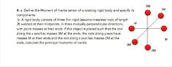
A rigid body consists of three thin rigid (assume massless) rods of length 21, welded at their midpoints, in three mutually perpendicular directions, with point masses at their ends. If this object is placed such that the rod along the x axis has masses 3M at the ends, the rods along y-axis have masses M at their ends and the rod along z axis has masses 2M at the ends, calculate the principal moments of inertia.

(See picture attached below)
Relevant Equations
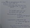
Picture attached below showcasing my attempt at the solution.
Hi.

So I was asked the following question whose picture is attached below along with my attempt at the solution.

Now my doubt is, since the question refers to the whole system comprising of these thin rigid body 'mini systems', should the Principle moments of Inertia about the respective axes be added together to give the solution in context of the 'total' rigid body systems? Or should we leave it by simply calculating the Principle moments of inertia for each body aligned at some axis about all the 3 axes?
 

Attachments

  • Screenshot_20210413-150137_Classroom.jpg
    Screenshot_20210413-150137_Classroom.jpg
    43.1 KB · Views: 155
  • Screenshot_20210413-150023_Classroom.jpg
    Screenshot_20210413-150023_Classroom.jpg
    43.3 KB · Views: 168
Physics news on Phys.org
1618310423206.png
what does this try to say ?

21 should be ##2L## (and ##a## should be ##0##) !

1618310286142.png
I don't see where the ##2\over 5## comes from ?

##\ ##
 
BvU said:
what does this try to say ?

For each pair of masses, the products of inertia turn out to be zero since the alignment is with the coordinate axes.

BvU said:
I don't see where the 2/5 comes from ?
That's the form for moment of inertia of a solid sphere about it's diameter which comes out as 2/5 M*R^2
 
warhammer said:
For each pair of masses, the products of inertia turn out to be zero since the alignment is with the coordinate axes.
Ah, 'pair' was hard to read. The off-diagonal elements of the ##I## tensor are zero, yes.
1618314977910.png


warhammer said:
That's the form for moment of inertia of a solid sphere about it's diameter which comes out as 2/5 M*R^2
There are no spheres, only point masses. There is no R.

1618315840534.png
So that is zero.
warhammer said:
should the Principle moments of Inertia about the respective axes be added together
Yes. For the complete rigid object you have to add all three ##I_{zz}##. See the definition here .

1618316033633.png
this last one is ##I_zz##

so you get ##I_{zz} = 8ML^2##. etc. All in all, not a very hard exercise, but good to go through at least once !##\ ##
 
BvU said:
Ah, 'pair' was hard to read. The off-diagonal elements of the ##I## tensor are zero, yes.
View attachment 281476There are no spheres, only point masses. There is no R.So that is zero.

Yes. For the complete rigid object you have to add all three ##I_{zz}##. See the definition here .this last one is ##I_zz##

so you get ##I_{zz} = 8ML^2##. etc. All in all, not a very hard exercise, but good to go through at least once !##\ ##
Thank you so much for your response. I'm summarising all the mistakes I made just to ensure all holes have been plugged:

1) Rather than spheres those are point masses. So moment of inertia of each is mr^2 where r is the perpendicular distance to rotation axis. Since 3M mass (for instance) is aligned at x-axis so it's I(xx) would be zero. Same would be true for 2M whose I(zz) & M whose I(yy) would also be zero respectively.

2) For the whole body, I need to add all the I(xx) , I(yy) & the I(zz) components together of the 3 rigid body pairs that are specified in figure.
Therefore for the whole the body,
I(xx)=6M*l^2
I(yy)=10M*l^2
I(zz)=8*M*l^2

Hope I've finally got this one right😅
 
  • Like
Likes BvU and hutchphd
Kindly see the attached pdf. My attempt to solve it, is in it. I'm wondering if my solution is right. My idea is this: At any point of time, the ball may be assumed to be at an incline which is at an angle of θ(kindly see both the pics in the pdf file). The value of θ will continuously change and so will the value of friction. I'm not able to figure out, why my solution is wrong, if it is wrong .
TL;DR Summary: I came across this question from a Sri Lankan A-level textbook. Question - An ice cube with a length of 10 cm is immersed in water at 0 °C. An observer observes the ice cube from the water, and it seems to be 7.75 cm long. If the refractive index of water is 4/3, find the height of the ice cube immersed in the water. I could not understand how the apparent height of the ice cube in the water depends on the height of the ice cube immersed in the water. Does anyone have an...
Thread 'A bead-mass oscillatory system problem'
I can't figure out how to find the velocity of the particle at 37 degrees. Basically the bead moves with velocity towards right let's call it v1. The particle moves with some velocity v2. In frame of the bead, the particle is performing circular motion. So v of particle wrt bead would be perpendicular to the string. But how would I find the velocity of particle in ground frame? I tried using vectors to figure it out and the angle is coming out to be extremely long. One equation is by work...
Back
Top