Understanding analog voltmeter calibration

  • #1
missionman
12
4
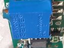
How did you find PF?: I have been trying desperately to correct a mistake I made when I received my new Zantum Class 0.5 10-15v voltmeter. The 2 screws on the back I thought were for wiring. Sure enough I found out they were calibration screws. I willy nilly began turning them thinking "is this the terminal point?". I still don't know how to wire it and now I've got a $50 paper weight meant to be installed for a parallel battey bank.
So here I am. That and I love programming scooter microcontrollers.

Hello everyone. Maybe you can help me screw my head on with understanding analog voltmeter calibration.

IMG_20240822_140641.png


IMG_20240822_140813.png
 
Last edited by a moderator:
Engineering news on Phys.org
  • #2
What about getting a known voltage source to calibrate and unscrewing the screws until the meter agrees with the source?

Then test on some other source to be sure.
 
  • Like
Likes davenn
  • #3
Welcome to PF.

missionman said:
The 2 screws on the back I thought were for wiring. Sure enough I found out they were calibration screws. I willy nilly began turning them thinking "is this the terminal point?". I still don't know how to wire it and now I've got a $50 paper weight meant to be installed for a parallel battey bank.
Which 2 screws? The 2 philips screws in what looks like a green terminal block? Can you upload a picture with more of a perspective of what that terminal block looks like? It looks like the wire access ports are toward the bottom in your picture...

Since there is a seal that says "calibration void if seal damaged" on the PCBA itself to the left of that terminal block, I'm guessing that those 2 terminal block screws do not have anything to do with calibration... (but the perspective picture is needed to be sure)
 
  • Like
Likes davenn and Lnewqban
  • #4
berkeman said:
Welcome to PF.


Which 2 screws? The 2 philips screws in what looks like a green terminal block? Can you upload a picture with more of a perspective of what that terminal block looks like? It looks like the wire access ports are toward the bottom in your picture...

Since there is a seal that says "calibration void if seal damaged" on the PCBA itself to the left of that terminal block, I'm guessing that those 2 terminal block screws do not have anything to do with calibration... (but the perspective picture is needed to be sure)
Yes these 2 screws on this green thing. Now I'm being told they ARE negative and positive terminals. This, after I was told they were calibration screws but I think they mistook thinking I meant the blue locktite set screws on top in the photo here I'm uploading.
EDIT: I can't seem to upload new photos. security error?

IMG_20240822_140849.png


IMG_20240822_140813.png


IMG_20240822_140719.png
 
  • #5
Can you upload a picture that shows that green terminal block and screws in perspective? Are there openings in the green terminal block for wires to be inserted?
 
  • #6
berkeman said:
Can you upload a picture that shows that green terminal block and screws in perspective? Are there openings in the green terminal block for wires to be inserted?
yes I had to edit my last repy. I uploaded 3 new photos
 
  • #7
Good, so yes those are just the screws for the terminal block for attaching the sensing wires to your battery.

Why do you think the meter is out of calibration? Have you attached it to anything yet?
 
  • #8
The seller on ebay for this Zantum Model ZAPV15B class 0.5 just told me the blue is the wire terminals. Is this correct? I think maybe he thought I was talking about the blue screws that are set in locktite that you see sticking out the top.
 
  • #9
berkeman said:
Good, so yes those are just the screws for the terminal block for attaching the sensing wires to your battery.

Why do you think the meter is out of calibration? Have you attached it to anything yet?
I guess this was a misunderstanding. The seller assumed I turned the blue terminals on top. So I guess its still in calibration. The BLUE set screws that are glued in place are the calibration screws.
Oh well this can help others hopefully.
 
  • Like
Likes berkeman
  • #10
Great! :smile:
 
  • Like
Likes missionman
  • #11
Having used that type of terminal strip in both blue as well as the green shown in your pix, it's possible the seller had seen both varieties.
 
  • #12
Averagesupernova said:
Having used that type of terminal strip in both blue as well as the green shown in your pix, it's possible the seller had seen both varieties.
Yes, in this case I think he assumed I turned the glued in place micro flat head screws.
Heres something really funny though. I understand now these screws on the green box are just back off and back on tension for the + an - connections or "sense" wires. However when the dial is perfectly tuned to zero, if i unscrew or screw in those screws it makes my needle go above zero. Then i have to adjust the screw to set it back to zero. Is this normal or is the zero screw on front way to sensitive, being a 0.5 class?
 
  • #13
That doesn't sound normal, so probably something else is going on. Like the mechanical stress of your torquing those connection screws is bending the overall structure or something like that. Take it easy on those screws! :smile:
 
  • Like
Likes Vanadium 50
  • #14
berkeman said:
Take it easy on those screws
You should use zero ugga-duggas on those screws.
 
  • Haha
  • Like
Likes missionman and berkeman
  • #15
missionman said:
Heres something really funny though. I understand now these screws on the green box are just back off and back on tension for the + an - connections or "sense" wires. However when the dial is perfectly tuned to zero, if i unscrew or screw in those screws it makes my needle go above zero. Then i have to adjust the screw to set it back to zero. Is this normal or is the zero screw on front way to sensitive, being a 0.5 class?
Maybe it is the way you support the meter while tightening the screw terminals.

Check that the new plastic (uncontaminated) front of the meter is not influencing the pointer through electrostatic charge. Wipe the front window with the tip of a dry finger, or approach it with a friction-charged ball point pen. Does the zero change?

If it does, dab one drop of glycol antifreeze (which is hygroscopic), on the window to discharge the surface charges. Only the smell of glycol is needed on the inside of the plastic to reduce the electrostatic influence.
 
  • Like
  • Informative
Likes Tom.G, berkeman and missionman
  • #16
Baluncore said:
Maybe it is the way you support the meter while tightening the screw terminals.

Check that the new plastic (uncontaminated) front of the meter is not influencing the pointer through electrostatic charge. Wipe the front window with the tip of a dry finger, or approach it with a friction-charged ball point pen. Does the zero change?

If it does, dab one drop of glycol antifreeze (which is hygroscopic), on the window to discharge the surface charges. Only the smell of glycol is needed on the inside of the plastic to reduce the electrostatic influence.
Thanks for this! Thats genius. This turned out to be the issue. The voltmeter was on my comforter on my bed developing static. I verified this by running finger over the cover and the super fine needle dropped! holy cow.
 
  • Love
Likes berkeman
  • #17
Previously having worked for a test equipment company I recall panel meters having trouble with static causing the needle to "stick" in places off of zero. Hadn't thought of that problem for a long time.
 
  • Like
Likes missionman
  • #18
Wow that is nuts! I also touch the back of the curicut board and the needle instantly falls back to zero!
So glad you told me this. this would've drove me mad had I not known. So this illustrates the importance of these 0.5 class voltmeters needing to be installed rather than handled. Slightest static causes the needle to "float" making it seem like it needs correction.
 
  • #19
missionman said:
Yes these 2 screws on this green thing. Now I'm being told they ARE negative and positive terminals. This, after I was told they were calibration screws but I think they mistook thinking I meant the blue locktite set screws on top in the photo here I'm uploading.
EDIT: I can't seem to upload new photos. security error?

View attachment 350261

View attachment 350262

View attachment 350263
Those blue things are trimpots. They do the calibration.
Like this:
Trimpot.png
 
  • Like
Likes missionman
  • #20
The Electrician said:
Those blue things are trimpots. They do the calibration.
Like this:
View attachment 350275
Yep, mine looks almost exactly like that only the screws have blue hardened epoxy glue or locktite on half of it. Same brass screws. Now i know not to touch that area. Thank you for all the valuable info.
 
  • #21
missionman said:
Slightest static causes the needle to "float" making it seem like it needs correction.
You only have to breathe on it, to discharge the electrostatic charge, but that condensation does not last, (unless you have very bad breath). The smell of dilute glycol, (less than one drop from the radiator of your car), is sufficient to make the clean plastic surfaces permanently hygroscopic.

Since external charges influence the internal surface charge distribution, the inner surface treatment is most important, but it only needs the smell of the glycol for lifelong protection from static, without causing corrosion, or gluing up of the jewel bearings. The charge distribution seems to attract the glycol vapour and moisture to condense where it is needed.

To lubricate a sealed mechanical clock, a small piece of cloth, felt, or paper, damp with light oil, can be placed inside the case. You can do the same with a sealed meter, but using glycol. The damp fabric provides a large condensation surface that can act as a capillary vapour storage during cold periods.

Glycol is NOT safe for use on high-voltage meters.
 
  • Like
Likes missionman
  • #22
OK im logging notes on this. My voltmeter is crucial. Its monitoring a battery bank RV set up. I already tried a SMD VM-1 analog LED voltmeter due to all the hype around it. I tested it against a cheap 2.5 class voltmeter, a $100 clamp meter an a $50 digital voltmeter on my batteries. They all read 13.44 volts or 13.4 volts on less fine readings. The SMD read 12.8v. A full 2 readings below the actual volts and the SMD had a reading ability of 13.4v, 13.1v then 12.8v.

I tested it many ways using different wire, oxygen free, cheap wire, 14g, 16g, and even close to battery and farther away, using relays not using relays with direct connection.
It was a huge disappointment. It also cost $80 bucks. Not worth it one bit. a $12 china made Baomain read 13.4v. So thats why I bought the Zantum 0.5 class.

And now im here learning more. This is the full reason how I ended up on physics forums. I knew the folks here knew a thing or 2.
 
  • Informative
Likes Tom.G
  • #23
I have not seen the internal electronics used with that meter, but judging from the non-linearity at the bottom of the scale, I would say that about 9.6 volts is being dropped by a Zener diode in series with the meter. It seems the Zener voltage is a bit off. It is possible that they may have adjusted meter physical zero to correct that. If that is the case, then when you adjust the zero, you upset the original calibration by those two divisions.

It would be interesting to see the circuit used to expand and calibrate the scale of that Zantum meter.

The voltage offset that expands the scale should come from a precision voltage reference, such as an LM4040 +5V device. Three of those, in series, would give you 10V and 15V references for use checking your meter. They are available in different accuracy grades.

I would use one or two of the LM4040 precision references to provide the 10V meter offset, and a third to establish a 15V full-scale check voltage. That would require the linearity at the bottom of the scale be corrected, by moving the 10V mark back to the physical zero.
 
  • Like
Likes missionman
  • #24
Very good points. this meter has a Barons 3296 square trimpot potentiometer. Its sealed meaning its almost solid state even though it has moving screws. It has 2 of these potentiometers. one sets the voltage at 10v within 0.01% accuracy. The other tops it at 15v, same deal. its a small scale but wide window for great accuracy. Its like the brain of the whole meter. Its calibrated at +0.01% increments which gives it that 0.5 class status. Anything better is thousands of dollars.
So according to the PDF on this trimpot, the calibration (accuracy) stays exact no matter what you do with the front zero setting dial. The zero doesn't cause a upset in the calibration, it merely resets whats called "mechanical zero". We hear this term used a lot in mechanical plumbing. Mechanical zero is totally independent of calibrated zero. Thankfully. So if I zero it to 1 volt it'll be 1 volt off but the internal resistors are still operating independent of what mechanical difference interferes. It'll still react according to the resistance feedback.
Things like static, shock (force), vibration can goof up mechanical zero quite often but the potentiometer continues its calibrated response.
I hope that answers some things.
 

Attachments

  • IMG_20240823_015011.jpg
    IMG_20240823_015011.jpg
    37.6 KB · Views: 6
  • #26
IMHO, you have two (2) input routes.
One is direct to the meter movement, whatever that is 'behind the label'.
The second is for the voltage-dropping / smoothing / protection etc to let that movement and range work in application.

I suspect your twiddling of the mounting screws has torqued the sensitive movement's suspension out of 'true'. Like clouting an analog watch or straining the bearings on a motor, it may never be 'happy' again.

Sorry, I reckon the best thing to do is to swear extensively, shrug and buy a new meter.
FWIW, I'd fit a modest 'digital' display along-side. Or, given their price, two. Yes, there will be small differences between these instruments' readings, but each device has its own strengths...
 
  • #27
No no no, I've already found that this green box is for the wires. There is nothing wrong with anything else.
I was only trying to figure out wiring on it.
The 2 blue trimpot potentiometers are the calibration points and they're fine :]
 
  • Like
Likes Nik_2213
  • #28
Given this is to be permanently installed I would go ahead and use it. Every now and again it can be verified with another voltmeter.
 
  • Like
Likes Nik_2213 and berkeman
  • #29
OK, slightly off topic, but...

One of the things I learned in a few decades of instrument/analog design is that anything that involves parts that move is imprecise, at least to some degree. They also have weird failure modes and they break before electronic devices. Panel meters look great and they are easy for humans to read quickly if they don't care about precision. But this sort of built in DVM is the way to go if you care about accuracy or reliability.

1724452951372.png


https://www.murata.com/products/productdata/8807021314078/20lcd-01-dcm.pdf?1583754809000

When was the last time you saw a new product from Keysight, Thermo-scientific, Beckman-Coulter, Agilent, Rohde & Schwarz, etc. That had a galvanometer on the front panel?

Having said all of that, I still have a warm place in my heart for these things. There are things they do that DMMs can't.

1724452425583.png


I'm glad to see they are still in business, but I'm not sure why. I wouldn't buy one.
 
  • Like
Likes berkeman
  • #30
DaveE said:
Having said all of that, I still have a warm place in my heart for these things. There are things they do that DMMs can't.

1724452425583.png
Yep. I've have a couple of them. :approve:
 
  • Like
Likes DaveE and berkeman
  • #31
Upside of 'Analog' is you may see needle twitch. No substitute for well-handled 'scope, but often a ''Huh ??'

Analogue or digital, you must be aware of wave-form, ripple etc etc and how instrumentation responds..

Sadly, this is a big problem with wannabe 'Over Unity' inventors: They embrace inappropriate readings...
FWIW, I was banned from a fun hobbyist electronics site for suggesting their resident 'Over-U' guru dispense with his wondrous array of mismatched instruments and simply attach a festoon of incandescent lights.
Given he was site's major sponsor, I was 'run out of town'...
 
  • #32
For service work, I use moving coil multimeters in preference to a digital multimeter.

With a DMM, the position of the decimal point is most critical, but is the least visible. Intermittent faults are very hard to find with a DMM. Servicing PWM systems with a DMM is fraught with sampling problems.

For 12V and 24V motor vehicle service, where there are connectors, moisture, dirt, salt, and vibration, a test lamp with a filament will be more honest and produce quicker results, than a high resistance DMM.

A DMM is only needed for setting up power supplies and calibrating instruments.
They are now so much cheaper than a moving coil meter, that DMMs are ubiquitous, and so will lead many beginners into trouble, wasting a lot of time.
 
  • Like
Likes Nik_2213, DaveE and Averagesupernova
  • #33
Baluncore said:
For service work, I use moving coil multimeters in preference to a digital multimeter.

My last couple Fluke DMMs at my last couple EE jobs had bargraph LCD displays in addition to their numeric displays. I usually found them to respond quickly enough to satisfy my need to see quickly changing numbers (well below oscilloscope needs). Have you used any DMM bargraphs like those?
 
  • #34
berkeman said:
Have you used any DMM bargraphs like those?
Yes, but the lower-cost non-fluke meters have slower bar-graphs, while unattended Fluke meters tend to go missing.

Bar-graphs also do silly things while range-switching induced by on-off intermittent signals. There are workarounds, but I am more interested in solving the problem than solving the test instruments.

It's horses for courses, I have low-cost versions of both types of meter at each workbench, and in each vehicle toolbox.

Everything is a compromise. If I need precision, I will use a reference grade meter, but it will not remain lying around, or being shaken in a vehicle.

I do appreciate the John Fluke Manufacturing company differential voltmeters, but I originally learned to read an AVO-8, so I guess moving coils are just an extension of my personality.
 
  • Like
Likes Nik_2213
Back
Top