Water Flow from Pressurized Tank through Heat Exchanger

  • #1
AxisCat
40
4
Homework Statement
none
Relevant Equations
none
Hi All-

New member here. As the title states I am trying to solve the flow volume of water from a pressurized storage tank through a heat exchanger and then discharging out the end of a pipe. I have been working on this for several days now without any luck, seems like now I am just throwing equations at it and hope something sticks. So I could use a nudge in the right direction.

The storage tank is a bladder tank in that air pressure is one side of the bladder and water on the other.

From the bottom of this tank the water flows through a heat exchanger. All I have on the heat exchanger to work with is (3) data points relating change in pressure with flow rate. I used curve fitting software to come up with a quadratic equation to describe this.

The water exits the heat exchanger and just empties into the open.

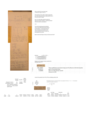
I have been using Bernoulli’s Equation to try and solve this. All my units should be a match. Volume in cubic feet, Area in square feet, pressure in pounds per square foot, density in pounds, time in seconds. Attached is a spreadsheet of my latest attempt. I apologize for how messy it is.

Thanks for you help!
Axis
 
Physics news on Phys.org
  • #2
Welcome to PF. I'm not seeing an attachment...

It's best not to try to attach files that can contain macros (Excel, Word, etc.). Instead, try to attach text files or PDF / JPEG copies of the work.

Thanks. :smile:
 
  • #3
berkeman said:
Welcome to PF. I'm not seeing an attachment...

It's best not to try to attach files that can contain macros (Excel, Word, etc.). Instead, try to attach text files or PDF / JPEG copies of the work.

Thanks. :smile:
Gotcha. Didn't think about that. The only way I could do some of the math easily is using excel.. But here is a PNG file of my work
 

Attachments

  • calculations.png
    calculations.png
    23.2 KB · Views: 51
  • #4
AxisCat said:
Gotcha. Didn't think about that. The only way I could do some of the math easily is using excel.. But here is a PNG file of my work
Put it right in the body of the response using the "insert image tool" (it looks like a little picture). It's too small to see (for me at least).
 
  • #5
Try this one
calculations.png
 
  • #6
AxisCat said:
Try this one View attachment 330525
hmmm, only a marginal improvement. Can you break it up into a few images? 1 for the diagram, 1 for the math, etc... they can all be inserted independently in the same way.
 
  • #7
Still having trouble getting the resolution right, Third time??
 

Attachments

  • calculations.png
    calculations.png
    33.5 KB · Views: 56
  • #8
AxisCat said:
Still having trouble getting the resolution right, Third time??
:olduhh: 
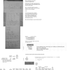
Sorry, no better. You are going to have to break it into a few separate images.
 
  • #9
The website is compressing my image files to a point they are too hard to read... let me try something else
 
  • Like
Likes erobz
  • #10
1.png
2.png
3.png
 
  • Like
Likes erobz
  • #11
Incompressible flow, uniform properties across the pipe,is the pipe the same diameter at 3 and 4?
 
  • #12
erobz said:
Incompressible flow, uniform properties is the pipe the same diameter at 3 and 4?
Correct on the statement and the diameters are the same
 
  • #13
I am not a student... not really in the math field. My algebra and physics was about 30 years ago.
 
  • #14
AxisCat said:
Correct on the statement and the diameters are the same
The pressure inside the jet, just outside the pipe almost immediately goes to atmospheric pressure. So ##v_4## is the jet velocity, and you can apply conservation of mass (continuity) to find ##v_3##. What do you get for ##v_3## if the cross sectional areas of 4 and 3 are the same?
 
  • #15
You should not be using the Bernoulli equation, since the pressure drop in the heat exchanger is mainly frictional pressure drop. Please show us the exact pressure drop vs flow rate data points you have.

In your calculations, I hope you recognize that pressure is in lbs force units and density is in lbs. mass units, and that you are using ##g_c=32\ \frac{lb_m\ ft}{lb_f\ sec^2}##

Are you just trying to add the pressure drop in the final discharge pipe and the gravitational heat in the tank to the pressure drop in the heat exchanger? What is the layout of the heat exchanger: single pass vs double pass, shell side vs tube side, tube diameter, number of tubes, total flow rate, etc.?
 
  • Like
Likes russ_watters
  • #16
erobz said:
The pressure inside the jet, just outside the pipe almost immediately goes to atmospheric pressure. So ##v_4## is the jet velocity, and you can apply conservation of mass to find ##v_3##.
That makes sense. So looking at how I set up my equation does it look right? The quadratic I am using is from curve fitting the pressure drop as a function of flow. I am not sure I can just set this equal to the change in pressure between point 4 and 1. And I don't know if it was correct to substitute the velocity by a volume/sec?
 
  • #17
Chestermiller said:
You should not be using the Bernoulli equation, since the pressure drop in the heat exchanger is mainly frictional pressure drop. Please show us the exact pressure drop vs flow rate data points you have.

In your calculations, I hope you recognize that pressure is in lbs force units and density is in lbs. mass units, and that you are using ##g_c=32\ \frac{lb_m\ ft}{lb_f\ sec^2}##

Are you just trying to add the pressure drop in the final discharge pipe and the gravitational heat in the tank to the pressure drop in the heat exchanger? What is the layout of the heat exchanger: single pass vs double pass, shell side vs tube side, tube diameter, number of tubes, total flow rate, etc.?

This is all the data i have on the heat exchanger, it is a single pass tube inside of a tube. Refrigerant on one side, water on the other. It is a ground source heat pump.

Intuitively I know the pressure drop in the heat exchanger is due to friction I guess I was hoping I could convert it to just pressure drop as a function of flow and then use the Bernoulli equations...

he.png
 
  • #18
AxisCat said:
That makes sense. So looking at how I set up my equation does it look right? The quadratic I am using is from curve fitting the pressure drop as a function of flow. I am not sure I can just set this equal to the change in pressure between point 4 and 1. And I don't know if it was correct to substitute the velocity by a volume/sec?
It doesn't look great. You should basically have a quadratic curve passing through the origin. i.e ##\Delta P(Q) = \beta Q^2 ## meaning if there is no flow there is no loss between points 2 and 3. You should be trying to force that form.
 
  • #19
erobz said:
It doesn't look great. You should basically have a quadratic curve passing through the origin. i.e ##\Delta P(Q) = \beta Q^2 ## meaning if there is no flow there is no loss between points 2 and 3. You should be trying to force that form.
Right, it was close to passing through the origin, i think rounding got it off some.
chart.png
 
  • #20
AxisCat said:
Right, it was close to passing through the origin, i think rounding got it off some.View attachment 330536
format the trendline for your original data, and set the origin to 0 for good measure.
 
  • #21
erobz said:
format the series, and set the origin to 0 for good measure.
Right... if i can loose the b and c coefficients it would be even simpler and just be (k)Q^2. but the K factor seemed to change with flow
 
  • #22
AxisCat said:
Right... if i can loose the b and c coefficients it would be even simpler and just be (k)Q^2. but the K factor seemed to change with flow
Exactly what you posted ΔP(Q)=KQ^2
 
  • #23
My goal is to determine a flow rate through this system based on a pressure inside the tank. As time moves forward the pressure in the tank will decrease along with the flow until the pressure inside the tank is equal to atmospheric pressure. I am trying to model that over time
 
  • #24
1692025277965.png


There is what I get, it doesn't perfectly fit theory, because that linear term isn't negligible.
 
  • #25
  • #26
AxisCat said:
Nice! Never thought about adding (0,0) then fit the curve
Its a trivial data point, you don't have to add it. You can just set the intercept to zero under formatting the trendline options.
 
  • #27
AxisCat said:
My goal is to determine a flow rate through this system based on a pressure inside the tank. As time moves forward the pressure in the tank will decrease along with the flow until the pressure inside the tank is equal to atmospheric pressure. I am trying to model that over time
Unfortunately, not such a trivial model to tackle... Also, all of the components have losses, not just the heat exchanger.
 
  • #28
What is the tube ID and what is the length and diameter of the exit pipe? What is the temperature of the fluid?
 
  • #29
erobz said:
Unfortunately, not such a trivial model to tackle... Also, all of the components have losses, not just the heat exchanger.
It sure has me stumped. Full disclosure. I am an HVAC contractor and have been installing geothermal heat pump systems since the early 1990's. I am probably counting piping buried in hundreds of miles by now. All closed loop. Closed loop is easy, just a circulator and component pressure loses. I have a customer who wants an open well and I said sure! I can do that. Bare in mind I have never done open loop and after hearing the well contractor start talking about 5 hp jet pumps and 100 gallon storage tanks I thought I better educate myself on the dynamics involved.
 
  • #30
If it was just geo unit and the well it becomes easy again... he wants to use the well for potable water too. The heat pump doesn't care about the pressure as long as it is above zero. And the 100 gallon storage tank really only has a usable draw down of about 35 gallons. My unit will drain that in about 3 minutes then the pump cycles on. All this above is really just me trying to understand the theory.
 
  • #31
AxisCat said:
It sure has me stumped. Full disclosure. I am an HVAC contractor and have been installing geothermal heat pump systems since the early 1990's. I am probably counting piping buried in hundreds of miles by now. All closed loop. Closed loop is easy, just a circulator and component pressure loses. I have a customer who wants an open well and I said sure! I can do that. Bare in mind I have never done open loop and after hearing the well contractor start talking about 5 hp jet pumps and 100 gallon storage tanks I thought I better educate myself on the dynamics involved.
Full disclosure, you probably should have done that before you accepted the work. :olduhh:
 
  • #32
erobz said:
Full disclosure, you probably should have done that before you accepted the work. :olduhh:
Hey I couldn't agree more but there has to be a first time for everything, right? If other people can do it there is no reason I can't as well. This is actually a small project compared to some larger ones I do. Make sense?
 
  • #33
AxisCat said:
If it was just geo unit and the well it becomes easy again... he wants to use the well for potable water too. The heat pump doesn't care about the pressure as long as it is above zero. And the 100 gallon storage tank really only has a usable draw down of about 35 gallons. My unit will drain that in about 3 minutes then the pump cycles on. All this above is really just me trying to understand the theory.
So you are trying to determine how long the storge tank will take to deplete to some minimum capacity when someone opens the tap?
 
  • #34
erobz said:
So you are trying to determine how long the storge tank will take to deplete to some minimum capacity when someone opens the tap?
Not really... the storage tank just keeps the water pressure between 60 and 40 psi. And with the 35 gallon draw down a tap can be open for quite a while before our pressure drops below 40 and the pump cycles back on. My unit will drain the tank in 3 minutes (roughly) before the pump cycles back on. A 5 hp pump draws more power than my entire unit. On any HVAC unit you want to maximize run times for effiecency and comfort. I don't want to short cycle the pump and need to be sure the pumping costs will not be more than my heating and cooling cost to operate.
 
  • #35
Also, I am not completely on my own with this. I plan to reach out to some of my experts for guidance on the design. I was just trying to understand the underlying math before I did so.
 
  • Like
Likes Tom.G

Similar threads

  • Engineering and Comp Sci Homework Help
Replies
22
Views
1K
  • Engineering and Comp Sci Homework Help
Replies
10
Views
2K
  • Engineering and Comp Sci Homework Help
Replies
12
Views
1K
Replies
2
Views
2K
  • Engineering and Comp Sci Homework Help
Replies
5
Views
1K
  • Engineering and Comp Sci Homework Help
Replies
12
Views
3K
Replies
50
Views
4K
  • Mechanical Engineering
Replies
15
Views
2K
  • Engineering and Comp Sci Homework Help
2
Replies
49
Views
2K
  • Engineering and Comp Sci Homework Help
Replies
1
Views
1K
Back
Top