- #1
ymnoklan
- 43
- 2
- Homework Statement
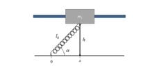
- Homework Statement: I have a cylinder of mass m1=5.0 kg sliding on a metal rod. Additionally it is connected to a spring with k=500 N/m. The height between the cylinder and where spring is connected is 0.30 m. I am asked to make a free-body diagram of the cylinder. The only forces I can identify immediately are gravity and the force from the spring, but I have a strong feeling there might be some more. What do you think?
Relevant Equations: G=m*g, F = k*x
- Relevant Equations
- G=mg, F=kx
G=mg (vertical down), F=kx (from the spring to the cylinder)