I Linear generator prototype

  • I
  • Thread starter Thread starter Micheal_Leo
  • Start date Start date
AI Thread Summary
The discussion focuses on testing a linear generator prototype using a galvanometer, with a specific configuration of a rectangular N28 magnet and a 0.6mm thick copper wire. Participants suggest measuring voltage with a voltmeter and emphasize that the magnet's movement must create a changing magnetic flux to induce voltage. Recommendations include using an oscilloscope to observe voltage changes and experimenting with different magnet orientations or configurations, such as combining magnets or using multiple coils. To achieve a consistent positive current for charging, a diode bridge is advised for rectification, along with potential enhancements like increasing wire turns or using a stronger magnet. Overall, the conversation highlights troubleshooting techniques and circuit improvements for effective voltage generation.
Micheal_Leo
Messages
103
Reaction score
4
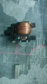
i want to just test a linear generator with galvanometer , the magnet is N28 and the wire (Cu) is of 0.6mm thikness and 10m long , but galvanometer dont show anthing ,

The core is PLA material (3d printed)
1758513272418.webp


The magnet size if 28mm * 10mm * 5mm
 
Physics news on Phys.org
Use a voltmeter (with an open circuit).
 
  • Like
Likes Micheal_Leo
What pole orientation does the magnet have?
How is the wire wound on the core?
What type of galvanometer, with what current range?

The flux through the core must change when the magnet is moved.
Have you considered measuring voltage, since V is proportional to the rate of change of flux.
 
  • Like
Likes Micheal_Leo
.Scott said:
Use a voltmeter (with an open circuit).
can i use oscilloscope?
 
Baluncore said:
What pole orientation does the magnet have?
How is the wire wound on the core?
What type of galvanometer, with what current range?

The flux through the core must change when the magnet is moved.
Have you considered measuring voltage, since V is proportional to the rate of change of flux.
Weixin Image_20250922115118_193_2.webp

the magnet is rectangular in shape so core is also in recatngular
 
Micheal_Leo said:
can i use oscilloscope?
Yes.
Micheal_Leo said:
the magnet is rectangular in shape so core is also in rectangular
When you slide the magnet through the core, the field does not reverse, so you get no voltage induced.
 
  • Like
Likes Micheal_Leo
Baluncore said:
Yes.

When you slide the magnet through the core, the field does not reverse, so you get no voltage induced.
so kindly how can i do , i should not use core , just coil and magnet ?
 
If the magnet is a bar with N-pole at one end and S-pole at the other, then to test the generator, turn the magnet, end for end, outside the coil, while watching the coil voltage.
 
  • Like
Likes Micheal_Leo
  • #10
You might try glueing two magnets together, NS+SN, to make a longer magnet, then drop them together through the one coil.

Alternatively, wind two coils in series on the same former. Wind one forwards and the other backwards. Space the coils apart by the length of the magnet.
 
  • Like
Likes Micheal_Leo
  • #11
With an oscilloscope set to the mV range and to trigger on any dV, rapidly swiping the N or S pole across the outside of (but close to) the windings should cause a trace. If it doesn't, get a powerful magnet (like what is used in hard data storage disks) and try again.
 
  • Like
Likes Micheal_Leo
  • #12
Baluncore said:
You might try glueing two magnets together, NS+SN, to make a longer magnet, then drop them together through the one coil.

Alternatively, wind two coils in series on the same former. Wind one forwards and the other backwards. Space the coils apart by the length of the magnet.
Perfectly got it. In linear generator i have seen that on galvanomter i get + and - mv. I would like to consider only positive current and use it for my charging purpose. So how can i do that
Thank you
 
Last edited:
  • #13
.Scott said:
With an oscilloscope set to the mV range and to trigger on any dV, rapidly swiping the N or S pole across the outside of (but close to) the windings should cause a trace. If it doesn't, get a powerful magnet (like what is used in hard data storage disks) and try again.
Yes same i did and it is working
Thank you
 
Last edited:
  • #14
Micheal_Leo said:
I would like to consider only positive current and use it for my charging purpose. So how can i do that
You can use a diode bridge to rectify the current so both the positive and the negative currents flow into the battery in the same direction.
https://en.wikipedia.org/wiki/Diode_bridge

You might consider a voltage doubling circuit, but winding more turns, moving the magnet faster or using a stronger magnet are alternatives.
https://en.wikipedia.org/wiki/Voltage_doubler

What voltage will the battery be charged to ?
What voltage does your generator make ?
 
  • Like
Likes Micheal_Leo
  • #15
Baluncore said:
You can use a diode bridge to rectify the current so both the positive and the negative currents flow into the battery in the same direction.
https://en.wikipedia.org/wiki/Diode_bridge

You might consider a voltage doubling circuit, but winding more turns, moving the magnet faster or using a stronger magnet are alternatives.
https://en.wikipedia.org/wiki/Voltage_doubler

What voltage will the battery be charged to ?
What voltage does your generator make ?
i have basically 4 linear generators , two on left two on right
i have selected N28 magnet and 0.65mm Cu wire(5m)
but galvanometer show no current at that stage

Generator video
 

Attachments

  • yu.webp
    yu.webp
    23.9 KB · Views: 4
  • #16
Micheal_Leo said:
can i use oscilloscope?
Very much so. Your Galvanometer needs to register a small positive and a small, equal amplitude negative spike as the magnet passes through the middle of the coil. If the needle is slow to react, it may be making a tiny twitch which you may not see. A 'scope will have a much greater bandwidth and should ;pick up much smaller and faster voltage variations.
This sort of experiment is often described in books (and by people who have never tried it) which fail to tell you practical details. For instance, if you let the magnet fall from half way down the coil, there will be only a positive (or negative) peak which a low spec meter could follow. What is the sensitivity of the meter? Are the 100,200,300 markings in mA? You could test the meter with another low voltage sourc. 'Dab' a 1.5V battery across it and see what happens.
PS Have you tried connecting across the G terminal and the black?
 
  • #17
The magnets of the type shown are common in both in variable reluctance motors and in linear motors. Invariably the magnetization vector is aligned through the short dimension of these magnets. When dropped through the coil as shown, I would expect the flux cut would very nearly cancel.
 
  • #18
Paul Colby said:
The magnets of the type shown are common in both in variable reluctance motors and in linear motors. Invariably the magnetization vector is aligned through the short dimension of these magnets. When dropped through the coil as shown, I would expect the flux cut would very nearly cancel.
So lengthening the dipole with a steel bar of a few cm (longer than the length of the coil) would help to give an effect.

One last (and possibly insulting suggestion - if so, I am sorry): The wire looks coppery and is it, in fact enamel insulated? Also, has the insulation at each end been cleaned off to actually produce a continuous circuit? Fine sandpaper does the job well. Sorry to the OP if I'm wrong but any port in a storm.

I was once given a non-working crystal set with a coil wound with uninsulated copper wire, to troubleshoot. So I have known the problem to arise.
 
  • #19
sophiecentaur said:
So lengthening the dipole with a steel bar of a few cm (longer than the length of the coil) would help to give an effect.
Moving the magnet he has on the outside of the coil might also increase the voltage generated. Putting a magnetic metal core through the coil and sticking the magnet to one end would also give a lager signal.
 
  • Like
Likes sophiecentaur
  • #20
Paul Colby said:
Moving the magnet he has on the outside of the coil might also increase the voltage generated.
We still don't know about the 'Galvanometer' and its time constant / dynamic behaviour. If the magnet is falling through the coil for a short enough time, the needle may not move fast enough for a twitch to be visible. My idea of lengthening the magnet was to widen the 'up/down pulse' as its field goes through.

The coil seems to have at least 100 turns so it really should produce something - even just waving it around the coil and, in particular, rotating it near one end. How can the detection be so insensitive? The case of the meter looks like you're expect with a regular milliammeter. It may be relatively sensitive to small currents but the dynamics count for a real galvanometer ( a wire suspension rather than conventional bearings and a very light movement).
 
  • #21
sophiecentaur said:
If the magnet is falling through the coil for a short enough time, the needle may not move fast enough for a twitch to be visible.
For a normal bar magnet magnetized along its long dimension, yes. However, I suspect the north (or south) pole of the magnet shown in post #5 is face up in the picture with the south (or north) pole laying face down against the table. Dropping this type of magnet through the coil will produce next to no voltage by symmetry, right?
 
  • #22
The actual pole pattern of the individual magnets is essential to this analysis and discussion. It would be helpful if the poles of the magnet could be mapped using a magnetic compass or another magnet, then marked on the surface of the magnet with red and blue marker pens.
 
  • #23
I finally viewed the movie clip in post #15. It’s difficult to tell the magnet orientation from the video. I now understand and agree with the comments about the galvanometer response time. A scope would be better. If the magnet shown in #5 was employed, Neither of the two possible orientations would give much flux change reciprocating like shown. Again, this is based on actually working with magnets like the ones shown. Of course it’s not possible for me to know just looking at a picture.

Back in the 90s I needed to make accurate measurements of the magnetic dipole moments of magnets that looked exactly like that shown. We did it by rotating the magnets in a home brewed Helmholtz coil and measuring the generated voltage with a multi meter. The rotation speed was several hertz which generated the better part of a volt. The technique worked very well.
 
Back
Top