Rogowski coil tension calculation formula

  • #1
arivel
43
1
Hi everyone .
I need help on the following problem.
I built a current sensor that is based on the same principle as the Rogowski coil. Don't propose other alternative methods to measure the current because its application will be different and I don't want to talk about this.
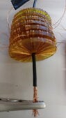
in reality what I built is a variant because it consists of 7 toroidal supports (in plastic material) wrapped in enamelled wire. each winding is connected in series with the others to form a larger one, the photograph is attached.
I made some measurements with an oscilloscope but I think the result displayed on the screen is wrong, which is why I would like to make a comparison with a mathematical calculation using the formula in the link: https://it.wikipedia.org/wiki/Bobina_di_Rogowski
to have a confirmation or denial of the measurement performed. I don't claim to obtain maximum precision, an error of less than 10% would be enough.
what I want to know is how much voltage comes out of the coil when I pass 0.5 A in the conductor with a frequency of 20 Hz.
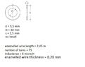
in the formula of the attached image taken from the link it doesn't seem to me that the Biot-Savart law is taken into consideration and I also don't know what value to give to L because in my case it is very variable due to the shape of the torus. if I measure L near the internal diameter it is much smaller than the L near the external diameter.
I calculated the area of the single copper coil but please check if the value is correct.
I hope I haven't left anything out.
bye thank you .
 

Attachments

  • current sensor.jpg
    current sensor.jpg
    20.4 KB · Views: 4
  • formula.jpg
    formula.jpg
    13.6 KB · Views: 3
  • toroidal support measure.jpg
    toroidal support measure.jpg
    27.1 KB · Views: 3
  • toroidal support.jpg
    toroidal support.jpg
    15.8 KB · Views: 5
Physics news on Phys.org
  • #2
arivel said:
I made some measurements with an oscilloscope but I think the result displayed on the screen is wrong, ...
1. Are your coils connected in series with the same polarity?

2. How did you integrate the signal from the series Rogowski coils?

3. Why do you have several toroids, when you could get the same multiplication by changing the capacitor value in the integrator?
 
  • #3
HI .
I have not applied any amplification with opamp integrator.
I want to know what comes out of the two terminals of the coils joined together without using opamp.
the coils are connected in series in the exact way, it's difficult to go wrong.
since the signal generated is very small, it is advisable to increase the number of toroids.
 
  • #4
no answer?
 
  • #5
The output voltage will be the derivative of the measured current, as written in your formula.jpg

If you included the op-amp integrator, you could easily calibrate the transfer function of your sensor coil.

With narrow rectangular coils, it is hard to calculate the area of a turn, and the magnetic field changes radially across the turn, so it is easier to measure the coefficient, than it is to calculate it.
 
  • #6
I have only one piece of information to ask.
To give a value to L do I have to take an average between the internal circumference and the external circumference multiplied by the number of toroids?
 
  • #7
If L is the length of each rectangular helix axis, then we must first find the effective radius, r, which will be somewhere between 3.5 mm and 30 mm.

The particular type of mean employed will depend on the magnetic field about the wire. Choose from the arithmetic AM, geometric GM, harmonic HM, or AGM ?
https://en.wikipedia.org/wiki/Mean#Types_of_means

As a first guess, I would use the geometric mean, but I would want to verify that choice before relying on the result.
r = GM( 3.5, 30 ) = √( 3.5 * 30 ) = 10.25 mm.
Maybe; L = 2⋅π⋅r = 64.4 mm.
 
  • #8
The number of coils, multiplied by the area of one coil, would be the same if you placed all your coil supports together, then wound one coil. It would significantly reduce the total length of wire needed.

Have you remembered to feed one terminal wire, back around inside the coil, to make a one ended "counter-wound" coil? Without that twist, your coils will pick up other stray fields.
 
  • #9
HI.
I'm not sure I understood the first sentence of your second post correctly.
did you write that a single toroidal support having the same length as the totality of all seven is better? i.e. 17.5 mm? .
there is a problem with the winding of the wire, it is much simpler to use a small thickness toroidal support instead of a large toroidal one, especially if I want to increase the overall number and reach a total length of 15 cm.
but it is possible to reach a compromise.
no I didn't pass a return wire inside the supports. For now I'm experimenting. I'll think about it when I've finished experimenting, and if I manage to obtain a result that I consider satisfactory.
 
  • #10
arivel said:
I'm not sure I understood the first sentence of your second post correctly. did you write that a single toroidal support having the same length as the totality of all seven is better? i.e. 17.5 mm?
The best cross-section for a coil is circular, a square is next best. That gives the maximum area of coil, for the minimum length of wire. The cross-section of your coils are rectangular, which is inefficient.

arivel said:
... did you write that a single toroidal support having the same length as the totality of all seven is better? i.e. 17.5 mm?
Yes, it generates the same voltage and requires less wire.

As an example, two of your coils in series, will produce the same voltage as one coil with twice the area. You could do that by placing two formers together, and winding one coil on that. The length of wire needed would be reduced significantly. The savings in wire, continue to increase, as you use more formers for one coil.
 
  • #11
why is the rectangular shape not efficient?
 
  • #12
arivel said:
why is the rectangular shape not efficient?
It uses too much wire.

Here are some calculations to show the advantage of wider coil formers.
The coil former section.
D = 30 mm ; d = 3.5 mm ; s = 2.5 mm.
Radial; R = (D-d)/2 = 13.25 mm
Width; S = 2.5 mm

The wire is wound on the outside of the former.
Wire diameter; w = 0.2 mm
R + w = 13.45 mm
S + w = 2.7 mm
Area of turn; A = (R+w)*(S+w) = 13.45*2.7 = 36.315
Circum' of turn; C = 2*(R+w+S+w) = 2*(13.45+2.7) = 32.3 mm
Area of coil; Ac = 75 * 36.315 = 2724. mm²
Wire on coil; Cc = 75 * 32.3 = 2422.5 mm

Area of two coils = 2 * 2724. = 5448. mm²
Wire on two coils = 2 * 2422.5 = 4845. mm

Now consider one coil on two formers.
R + w = 13.45 mm
S + w = 5.2 mm
Area of turn; C = 13.45 * 5.2 = 69.94 mm²
Circum' of turn; C = 2*(13.45+5.2) = 37.3 mm
Area of coil; Ac = 75 * 69.94 = 5245.5 mm²
Wire on coil; Cc = 75 * 37.3 = 2797.5 mm

Note that the area has fallen, 5448 to 5245.5 = 96.3%
The length of wire has fallen, 4845 to 2797.5 = 57.7%
There are greater advantages with a square section, when S ≈ R.
 
  • #13
therefore if I use a square toroidal support having the area of the single coil of wire with the following measurements: 13.25mm x 13.25mm.
is it the optimal solution?
 
  • #14
Do the numbers.
R = 13.25 mm
S = 13.25 mm
R + w = 13.45 mm
S + w = 13.45 mm
Area of turn; A = 13.45*13.45 = 180.9 mm²
Circum' of turn; C = 4 * 13.45 = 53.8 mm

Area of coil; Ac = 75 * 180.9 = 13568. mm²
Wire on coil; Cc = 75 * 53.8 = 4035. mm
That will cost less, and be much easier to wind.
 
  • Like
Likes arivel
  • #15
Thank you
 

Similar threads

  • Electromagnetism
2
Replies
43
Views
2K
Replies
13
Views
2K
  • Electromagnetism
Replies
16
Views
2K
Replies
6
Views
2K
  • Electrical Engineering
Replies
9
Views
1K
Replies
4
Views
3K
  • Electrical Engineering
Replies
8
Views
4K
  • Engineering and Comp Sci Homework Help
Replies
5
Views
2K
Replies
8
Views
2K
Back
Top