- #1,716
hallpa00
- 4
- 0
RM - many thanks for the advice. I will do as you suggest and report back in 12 days!
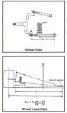
RM- thank you for last few responses for me. I finally made it out to practice and my car actually rotates in the middle of the corner which is amazing since i have always been fighting with tight tight tight in the center of the corner. however i am slightly tight entering the corner and my RF tire is average 23 deg. more than the RR. I was thinking from all ive read through these posts that i might take out the RF spring of 325 that you recommended in my prior post and go to a 300 on the RF and go from there. Is that a good idea and would that ruin my center of corner? Also just curious as to your adjustments processes at the track or if there is a post you can direct me too that I might have missed on this thread. Thanks again!Ranger Mike said:bar is 145# at maximum 14" arm length
170# at 13" arm length
202# at 12" arm length
222# at ideal length of 11 1/2"
at 11 Inch arm length bar has spring rate of 243# , write all these setting down so you can tune at the track.
https://www.gtsparkplugs.com/Sway-Bar-Calculator.html
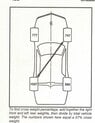
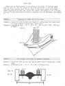
once the Roll center located and ARB and spring package it close to ideal we tune with the front ARB and rear panhard bar to fine tune. The car (on paper) is set up optimally. Now the real world influences like track banking, track conditions can be adjusted for. The other racers will have to fight flakey 3rd link problems ( too much left rear load has to be compensated with stiffer right rear springs and does not really fix the problem), lack of right front down force because they got no ideal body roll to add downforce. You have taken the time to fix camber build, bump steer, rear roll steer, maximum left side weight. car is as good as anyone can make it. Now you are fighting the weather and the track.
No sway barRanger Mike said:alph, welcome
Issues:
What size ARB (sway bar) in front??? solid sway bar i assume. what diameter, what length? any preload?
What are camber settings?
Have you checked to see if rear end is bent?
Loose mid of bad in slick ?????
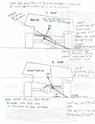
Photo of Roll center lay out says it is located to the left of center. You said it was on passenger side???
Lowers can be raise but bower moved down. ?????? what the heck??
please review spelling of your post so we can discuss
I believe I had a small frame rub on that RR. Forgot to include that in my response. That would cause the increase in tempRanger Mike said:can you put another spindle nose on the right rear quick change tube that has camber? A 36° difference from inside to outside temps on the rt rear is huge. Should be within 10°
the inside tread edge is burning off!
Here’s where the fun part is in my general curiosity:Ranger Mike said:I would say you are in a very good position. Roll center is ok so corner entry should be good as you u stated. You know the problem on rt rear regarding tire temps. It still looks like a spring change though. cannot tell until the tires are at best camber, inflation so total spread from inside middle and outside is 10° on spec tires. Typically, the right rear temp average should be between 10 to 15° cooler than the right front average. Seriously consider the springs recommended.

No sir. Big spring carRanger Mike said:are you running coil overs on front?
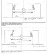
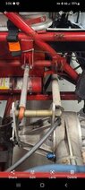
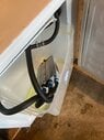
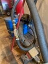
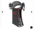
I think I’ve discovered a major issue. The LF has a 2.25” drop roll bar upper shock mount so it’s pushing the whole shock down and The shock is bottoming out. Here is what it has currently and I’m going to change it to a roll bar swivel style (yes, I know the phot is of a different roll bar diameter lol)alpharomeofifetwo said:LF static compression 1” + 3.25” dynamic =
Been doing my due diligence on this refrigerator with wheels the past two days, love some good math problems.Ranger Mike said:so i still think you are too soft on frt springs but we have to get
I’ll have to get you that information later tonight or next weekend. I’ll measure middle of inner pivot point -> center of spring then inner pivot to outer ball joint. MR= D1 / D2Ranger Mike said:what is motion rate of the spring? huge!!
i assumed you were running stock A-arms. are you running slider attached at different angles and mount point from stock?
I’m slowly coming to terms with this idea.Ranger Mike said:If you have GM metric A-Arm and have 700# spring in stock location
not enuff, too nose heavy , loose off