Understanding Surge Protector Specs for the Computer Age

  • Thread starter kiki_danc
  • Start date
In summary, the Mean Well RS-50-24 can withstand a 300VAC surge input up to 5 seconds. To determine the joules it can protect against, multiply the volts (220) by the joules (680).
  • #36
The installer returned asap to put the cable clamp (although I think the term is more like tube protector?).

8HPC6F.jpg


I noticed the wires running from the top to the circuit breaker is about 1 foot. I think the requirement is it should be 6 inches or the VPR would increase? Need to check computation so can let installer make changes to the orientation and wire length.

Anyway. After some pondering... it seems the lower clamping voltage of 500 volts in the white strip surge protectors is equivalent to the higher clamping voltage of the SPDs of 1200 volts. This is because the former uses UL 1339 3rd edition test vector of 6000 volts but only 0.5 kA while the latter test uses UL 1339 4rd edition 6000 volts and 3 kA.. 6 times more... both test still use the 8/20 µs surge pulse.

https://library.e.abb.com/public/1e3ee76b6b93d21ac1257a0f005711d1/Leaflet%20UL1449_Surge%20Protection%20Devices_1TXH%20000%20106%20L0201.pdf quoting:

"The measured voltage protection level. One of the last changes found in the new UL 1449 3rd Edition, is the modification in the measured voltage protection level. The Measured Limiting Voltage (MLV) is the maximum magnitude of voltage measured at the application of a specific impulse wave shape. When applying a certain surge current on the SPD the measured voltage at the device terminals is the so called “let-through voltage.” In UL 1449 2nd Edition, the let-through voltage was referred to as Suppressed Voltage Rating (SVR) and was calculated with a 0.5 kA surge wave form at 6 kV. The new designation is Voltage Protection Rating (VPR) and is calculated with a 3 kA surge wave form at 6 kV.
The MLV will allow comparison of different types of SPDs with regards to the let-through voltage. However, it is important to

Here is another good reference.

https://ewh.ieee.org/r3/nashville/events/2011/Surge Protection Device Standards - IEEE Meeting.pdf

so the 1200 volts is a new standard.. but won't it damage 220 volts equipments.. let's compute... Rive.. more reference welcomed.. thanks..
 

Attachments

  • 8HPC6F.jpg
    8HPC6F.jpg
    21.5 KB · Views: 505
Engineering news on Phys.org
  • #37
Rive said:
To put those wires in context I believe this part of the previously linked document will be relevant:
214220-a5ea9570820a102521449496d5df4654.png
That fits in nicely with the UL (Underwriters Laboratory) requirement that a type 3 SPD have a minimum of 10 meters of wire betwen it and the type 2 device. That extra 10μH of inductance will really cut the voltage hitting the type 3 SPD.
 

Attachments

  • 214220-a5ea9570820a102521449496d5df4654.png
    214220-a5ea9570820a102521449496d5df4654.png
    1.6 KB · Views: 482
  • Like
Likes kiki_danc and Asymptotic
  • #38
Rive said:
To put those wires in context I believe this part of the previously linked document will be relevant:
View attachment 231139
view.php

Got a point. So I scheduled the installer to remove the extra metal box and put the SPD right inside the main panel with only 2 inches of lead wires... do you know the formula why impedance can increase the voltage?
 
  • #39
Tom.G said:
That fits in nicely with the UL (Underwriters Laboratory) requirement that a type 3 SPD have a minimum of 10 meters of wire betwen it and the type 2 device. That extra 10μH of inductance will really cut the voltage hitting the type 3 SPD.

Extra wires are supposed to increase the voltage.. not decrease it.. why did you state inductance can decrease voltage? In the voltage-inductance formula.. did it increase or decrease the voltage?

5g5qO6.jpg


I'd let installer attempt the third. It is supposed to decrease the voltage protection level...
 

Attachments

  • 5g5qO6.jpg
    5g5qO6.jpg
    57.1 KB · Views: 505
  • #40
kiki_danc said:
Extra wires are supposed to increase the voltage.. not decrease it.. why did you state inductance can decrease voltage?

As was stated by @Rive (https://www.physicsforums.com/goto/post?id=6062201#post-6062201), there is a voltage drop across the wires to the SPD. If you have a type 2 SPD at the circuit breakers, 10m of wire, and a type 3 SPD connected directly at the protected device, you get that voltage drop across those 10m wires when the type 3 SPD conducts. This decreases the current and voltage at the protected device, giving you better protection and less stress on the type 3 SPD.

That's how SPDs work, at high voltage they put a short circuit across the wires and count on the impedance of the conductors back to the source to drop the voltage. (or they die trying :oldsmile:)

Cheers,
Tom
 
  • #41
Tom.G said:
As was stated by @Rive (https://www.physicsforums.com/goto/post?id=6062201#post-6062201), there is a voltage drop across the wires to the SPD. If you have a type 2 SPD at the circuit breakers, 10m of wire, and a type 3 SPD connected directly at the protected device, you get that voltage drop across those 10m wires when the type 3 SPD conducts. This decreases the current and voltage at the protected device, giving you better protection and less stress on the type 3 SPD.

That's how SPDs work, at high voltage they put a short circuit across the wires and count on the impedance of the conductors back to the source to drop the voltage. (or they die trying :oldsmile:)

Cheers,
Tom

But this doesn't seem to answer the question why putting the SPD right inside the panel circuit besides the breaker would decrease the VPR or Up.

First some definitions so we are on the same page.

vf07C4.jpg


If the leads from the SPD is short.. the Up (voltage protection level) is lower. Why? how do you relate this to impedance and what is the formula(s) involved?
 
  • #42
kiki_danc said:
I'd let installer attempt the third. It is supposed to decrease the voltage protection level...
Just still keep in mind the local code.
Also, the previously linked document has some wiring/placement suggestions too.

kiki_danc said:
If the leads from the SPD is short.. the Up (voltage protection level) is lower.
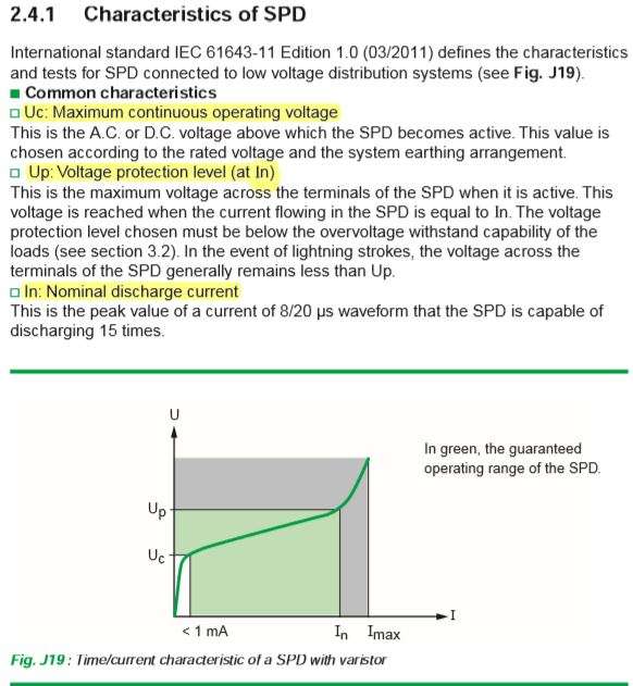
The linked picture is about the characteristics of the SPD: that Up is measured on the terminals of the SPD. But since you will use the SPD in an assembly, you have to care about the Up of the assembly (mentioned as 'installed Up'), what will consist of the Up of the SPD and the voltage drop on the wires. About the voltage drop on the wires there was a shortened calculation (with the laws mentioned) on the attachment of post #35

View attachment 231139
 
  • #43
Rive said:
Just still keep in mind the local code.
Also, the previously linked document has some wiring/placement suggestions too.The linked picture is about the characteristics of the SPD: that Up is measured on the terminals of the SPD. But since you will use the SPD in an assembly, you have to care about the Up of the assembly (mentioned as 'installed Up'), what will consist of the Up of the SPD and the voltage drop on the wires. About the voltage drop on the wires there was a shortened calculation (with the laws mentioned) on the attachment of post #35

View attachment 231139

The attachment is very clear that "As a result, the voltage across the equipment terminals, installed Up, is: installed Up = Up + U1 + U2... " and "... the voltaqe across the equipment terminals will be Up + 500". So longer wires can result in high Up in the installed terminals and UL recommends using very short lead wires. Why do you keep saying the Up will be lower if longer wires or voltage drop??
 
Last edited:
  • #44
A geezer trick (from a geezer who designed TVSS equipment in the distant past, FWIW): I sometimes use the 'power strip' type protectors in my house. I always tie as tight a knot as physically possible in the supply cord.
 
  • #45
Many countries have standards that equipment must meet. For computers in Europe I think it's EN 50081. Many decades ago I got involved with testing equipment by sending spikes down the mains. It was usually easy to prevent damage ocuring but harder to stop the computer or microprocessor inside crashing or causing data corruption. Fitting filters or suppressors in the power supply isn't always the cure. Sometimes the spikes "couple" into cables or other interconnections.

Edit: that standard has been replaced by EN61000.
 
  • #46
Let me clarify something:

cJdBx0.png


The above was describing the fact that longer wires cause greater Up or VPR. Yet Tom.G and Rive spoke of voltage drop in a third SPD about 10 meters away from it. Can they or others confirm that they were describing separate fact not being described in the above image? This is important to me because I may do both: Shorten the wires between SPD and breaker and add a second SPD 10 meters away right at equipment (but it's more expensive than the one I bought so need more hard facts). The following graphics showed that shorten lead wires between SPD and breaker can lessen the VPR. And I think this was also being described above (and not about this fact about voltage drop 10 meters away from the SPD which Tom. G and Rive may be confusing the two in the image intended for the VPR increase for longer lead wires between SPD and breaker (?). Another good illustration in the Schneider Electric page.

RHSTeb.jpg
 

Attachments

  • cJdBx0.png
    cJdBx0.png
    37.2 KB · Views: 575
  • RHSTeb.jpg
    RHSTeb.jpg
    40.7 KB · Views: 633
  • #47
Rive said:
To put those wires in context I believe this part of the previously linked document will be relevant:
View attachment 231139
view.php

Rive.. you omitted the left description in the attachment above.. the complete one is:

EOLza2.jpg


The left caption quoted: "Connections of a SPD to the loads should be as short as possible in order to reduce the value of the volage protection level (installed Up) on the terminals of the protected equipment."

This seems to be in conflict of your statement that the installed Up would be lower if longer wires (10 meters) are used. Even if you use an SPD type 3 beside the equipment that is 10 meters from the breaker.. won't the effect be like it's 10 meters distance between the SPD and breaker giving rise to huge increases in the Up?

I spent the last 1.5 hours googling all this but can't find the relevant information about this alleged decrease in the voltage with longer length instead of increase so please clarify more clearly. Thank you.
 

Attachments

  • EOLza2.jpg
    EOLza2.jpg
    62 KB · Views: 557
  • #48
Tom.G said:
As was stated by @Rive (https://www.physicsforums.com/goto/post?id=6062201#post-6062201), there is a voltage drop across the wires to the SPD. If you have a type 2 SPD at the circuit breakers, 10m of wire, and a type 3 SPD connected directly at the protected device, you get that voltage drop across those 10m wires when the type 3 SPD conducts. This decreases the current and voltage at the protected device, giving you better protection and less stress on the type 3 SPD.

That's how SPDs work, at high voltage they put a short circuit across the wires and count on the impedance of the conductors back to the source to drop the voltage. (or they die trying :oldsmile:)

Cheers,
Tom

Reviewing about Impedance. It acts like resistance and only valid for high frequency in a straight wire. So you are saying that 10 meters between the equipment and the SPD type 2 install breaker can decrease the residual high frequency surge voltage. But what if you don't add a type 3 a the equipment and just make sure it's 10 meters between them. How much would the 1200 volts VPR output at the Spd type 2 at breaker decrease when it moves through the impedance of the 10 meter length to the equipment (without SPD type 3 present at equipment)?

Presently. The distance between my Type 2 SPD at breaker to equipment is only 5 meters. If I add another 5 meters to make it 10 meters. What would happen to the VPR at the equipment? Would it decrease from 1200 volts to 600 volts (even without type 3 spd installed).

And I understand that if I add a type 3 spd at equipment, the impedance of the 10 meter distance is what segregate it such that the SPD type 3 at equipment would only see the 1200 VPR output of the spd type 2 at breaker and not the full high voltage surge from the strike? If it sees only the 1200 VPR at the breaker then adding type 3 could bring it down to normal 220 volts (or 220.001 volts) VPR at equipment.

I asked the suppliers of SPDs in my place and they are not familiar with the technical. One of them doesn't even know the meaning of SCCR or In or about impedance mismatched. They just sell you the SPDs and install it (this is why the wiring in my installed SPD is very long because they ignore all this important technical detail). I even asked directly the manufacturer of Prosurge, the region sale head is not very familiar and asked me to ask my local supplier (who doesn't know the details).
 
  • #49
kiki_danc said:
This seems to be in conflict of your statement that the installed Up would be lower if longer wires (10 meters) are used.
There is no conflict at all. You just repeatedly mistaking the wires used to install the type2 SPD into the switchbox with wires connecting the switchbox to the protected equipment (which hopefully has a type3 SPD).

By the way the letter type of 10m wire was the contribution of @Tom.G in post #37.

Ps.: due 'omitting' and such I don't really feel like putting any more effort here.
 
  • #50
Rive said:
There is no conflict at all. You just repeatedly mistaking the wires used to install the type2 SPD into the switchbox with wires connecting the switchbox to the protected equipment (which hopefully has a type3 SPD).

By the way the letter type of 10m wire was the contribution of @Tom.G in post #37.

Ps.: due 'omitting' and such I don't really feel like putting any more effort here.

Googling further. I found the following text and image which seems to suggest that longer wires (whether between type 2 spd and switchbox or between switchbox to the protected equipment) can both lead to voltage increase (not decrease in the case of the latter)...

http://engineering.electrical-equip...ution/lv-coordination-2-surge-protectors.html

"If the length of cable between the “main” surge arrester and the equipment to be protected is too long, oscillations and wave reflections may lead to tensions in the equipment; these tensions can be above the Up level of the same surge protector (until doubled up)

Next figure is : Voltage curve at the end of the cable depending on length of cable (front voltage =4kV/µs)"

Pq6Tkd.jpg


If one will still state that 10 meters can cause voltage drop from the impedance (Tom G).. please show proof or calculations or reference because I have googled a lot and I just can't find the reference the wires between the switchbox and equipment can cause voltage drop (the above shows there is voltage increase instead). This is important for sake of discussion and facts.
 

Attachments

  • Pq6Tkd.jpg
    Pq6Tkd.jpg
    23.5 KB · Views: 559
  • #51
kiki_danc said:
And I understand that if I add a type 3 spd at equipment, the impedance of the 10 meter distance is what segregate it such that the SPD type 3 at equipment would only see the 1200 VPR output of the spd type 2 at breaker and not the full high voltage surge from the strike? If it sees only the 1200 VPR at the breaker then adding type 3 could bring it down to normal 220 volts (or 220.001 volts) VPR at equipment.
You've got 99% of it right.
The type 3 at the equipment will bring the surge down to whatever its protection voltage is, and the type 3 SPD can have a lower energy rating than the type 2 in the breaker box.

ADDENDUM:
Hmm, we were typing at the same time. Your most recent post (#50) is for the case where you have the SPD in the breaker box but do NOT have one at the equipment to be protected. That's another reason to have an SPD as close to the equipment as possible, it eliminates those reflections and possible voltage doubling.

If needed, I'll post a sketch tomorrow (or maybe later today).

Cheers,
Tom
 
  • Like
Likes kiki_danc
  • #52
Tom.G said:
You've got 99% of it right.
The type 3 at the equipment will bring the surge down to whatever its protection voltage is, and the type 3 SPD can have a lower energy rating than the type 2 in the breaker box.

ADDENDUM:
Hmm, we were typing at the same time. Your most recent post (#50) is for the case where you have the SPD in the breaker box but do NOT have one at the equipment to be protected. That's another reason to have an SPD as close to the equipment as possible, it eliminates those reflections and possible voltage doubling.

If needed, I'll post a sketch tomorrow (or maybe later today).

Cheers,
Tom

The following SPD type 3 is being offered to me:
CgbtoV.jpg


YE6d0n.jpg


If it can bring the 1200 Volts VPR in the Spd type 2 in the breaker to 220 volts in the equipment.. then I'd purchase it asap even if it's more expensive than the type 3. Also it's installed as series.. this is ok?

But do you know how UL computes the 10 meters length to be used as impedance to lower the voltage in the type 3? The supplier doesn't know. My existing length between breaker to equipment is just 5 meters. If you can show 10 meters is necessary. Then I'll add 5 meters by looping it in the side to satisfy the UL requirements. Thanks.
 

Attachments

  • CgbtoV.jpg
    CgbtoV.jpg
    29.3 KB · Views: 608
  • YE6d0n.jpg
    YE6d0n.jpg
    61.8 KB · Views: 431
  • #53
kiki_danc said:
If it can bring the 1200 Volts VPR in the Spd type 2 in the breaker to 220 volts in the equipment.. then I'd purchase it asap even if it's more expensive than the type 3. Also it's installed as series.. this is ok?
The datasheet you posted says VPR <1KV and it starts to clamp around 370V, probably as low as you can find for a 220/277V rated device. Notice that the maximum continuous power line voltage is 320V.

Series is OK for this one. As shown in the schematic, internally the SPD components are installed across the power line. Because it has exposed metal connected to the power line, this device is designed to be mounted in an electrical box or in the protected equipment itself. Just be sure it is installed close to the equipment you want to protect.

kiki_danc said:
But do you know how UL computes the 10 meters length to be used as impedance to lower the voltage in the type 3?
No I don't know how they came up with 10 meters but that is one of the requirements to meet Type 3 SPD standards in UL-1449. Here is the link to the UL page which has a short description, you can research further from there. https://standardscatalog.ul.com/standards/en/standard_1449

If you are rich they will sell you a copy of the complete standard starting at USD $716. You may be able to find a lower cost copy of whatever standard is used in your country. Sometimes a Google search will turn up free copies of a standard.

Cheers,
Tom
 
  • #54
Tom.G said:
The datasheet you posted says VPR <1KV and it starts to clamp around 370V, probably as low as you can find for a 220/277V rated device. Notice that the maximum continuous power line voltage is 320V.

Series is OK for this one. As shown in the schematic, internally the SPD components are installed across the power line. Because it has exposed metal connected to the power line, this device is designed to be mounted in an electrical box or in the protected equipment itself. Just be sure it is installed close to the equipment you want to protect.No I don't know how they came up with 10 meters but that is one of the requirements to meet Type 3 SPD standards in UL-1449. Here is the link to the UL page which has a short description, you can research further from there. https://standardscatalog.ul.com/standards/en/standard_1449

If you are rich they will sell you a copy of the complete standard starting at USD $716. You may be able to find a lower cost copy of whatever standard is used in your country. Sometimes a Google search will turn up free copies of a standard.

Cheers,
Tom

This is the continuation of the specs that is cut due to screen size limit:

gNDtXq.jpg


As you can see, it's Approval and Certification is only CE.. Not UL.. my installed Prosurge model has UL, KEMA certification. Do you think surge protector with only CE approval and not UL is not fully tested? Because I only heard about UL 1449 4th Edition where they change the name of TVSS to SPD. The CE approval process or body doesn't seem to involve SPD. What do you make of this? And do you think UL tested every device that has UL approval?

Another thing. For main circuit breaker.. do you think 50kA Imax is enough? Can surge discharges from outside occur more than 50kA sometimes? If so, then I'll get a 100kA to be put in the main breaker and the 50kA transferred to my equipment as the above type is only 25kA and if I'm hit with surges above 50kA then both would get fried.
 

Attachments

  • gNDtXq.jpg
    gNDtXq.jpg
    24.8 KB · Views: 432
  • #55
kiki_danc said:
Do you think surge protector with only CE approval and not UL is not fully tested?
Below is from the last paragraph of: https://ec.europa.eu/growth/single-market/ce-marking_en
Please note that a CE marking does not indicate that a product have been approved as safe by the EU or by another authority.

The complete KEMA certifications is the GOLD certificate where tests are performed in the KEMA labs compliance with standards and documentation. Other levels are SILVER and GREY, which are not as complete.
Here is an excerpt from the KEMA website. (https://www.dnvgl.com/energy/laboratories/reports.html)
Gold: KEMA Type Test Certificate
A KEMA Type Test Certificate is issued when all tests are carried out successfully at KEMA Laboratories in accordance with a recognized standard the technical drawings have been verified and a visual inspection has been carried out. To receive this certificate, the equipment tested must fulfill all the requirements of the standard and the relevant ratings assigned by the manufacturer.


Underwriters Laboratories (UL) performs tests in their own labs and addresses mainly safety issues. UL was started by the insurance companies to decrease their losses from poor, unsafe products.

kiki_danc said:
And do you think UL tested every device that has UL approval?
UL tests products for compliance to the UL safety specifications, this is done on either a prototype or on "typical" products taken from a production line. If it passes, the product is assigned a number and the manufacturer gets the right to advertise that and to affix a UL label to the product. UL does not continuously inspect products being manufactured, and I seriously doubt that any of the other agency would either.

kiki_danc said:
do you think 50kA Imax is enough?
I have no idea. Ask your power company or the agency that regulates your power company, or maybe the manfacturer of your circuit breakers.

You seem to be looking for absolute protection from power line surges. There is no such thing. A few years ago a tall flagpole about 80feet (25m) away was struck by lightning. My computer equipment was on the second floor protected by SPDs and a battery powered Uninterruptable Power Supply (UPS). Most of the equipment survived, but the printer died. Apparently the data cable between computer and printer had enough voltage directly induced in it from the lightning strike to damage the printer.

The closest you can get to absolute protection is your own generator (maybe with battery backup) inside a well grounded metallic enclosure that also contains you protected equipment, no wires entering or exiting to the outside, and Lightning rods around it. That will work until the control circuit on the generator fails. :frown: (Data transmission to/from the outside with optical cables.)

The KEMA and CE info above was found with simple Google searches that you can do, as was some of the earlier UL info. I will start suggesting you do that for your future easily found questions.

Cheers,
Tom
 
  • Like
Likes kiki_danc and krater
  • #56
Tom.G said:
Below is from the last paragraph of: https://ec.europa.eu/growth/single-market/ce-marking_en
Please note that a CE marking does not indicate that a product have been approved as safe by the EU or by another authority.

The complete KEMA certifications is the GOLD certificate where tests are performed in the KEMA labs compliance with standards and documentation. Other levels are SILVER and GREY, which are not as complete.
Here is an excerpt from the KEMA website. (https://www.dnvgl.com/energy/laboratories/reports.html)
Gold: KEMA Type Test Certificate
A KEMA Type Test Certificate is issued when all tests are carried out successfully at KEMA Laboratories in accordance with a recognized standard the technical drawings have been verified and a visual inspection has been carried out. To receive this certificate, the equipment tested must fulfill all the requirements of the standard and the relevant ratings assigned by the manufacturer.


Underwriters Laboratories (UL) performs tests in their own labs and addresses mainly safety issues. UL was started by the insurance companies to decrease their losses from poor, unsafe products.UL tests products for compliance to the UL safety specifications, this is done on either a prototype or on "typical" products taken from a production line. If it passes, the product is assigned a number and the manufacturer gets the right to advertise that and to affix a UL label to the product. UL does not continuously inspect products being manufactured, and I seriously doubt that any of the other agency would either.I have no idea. Ask your power company or the agency that regulates your power company, or maybe the manfacturer of your circuit breakers.

You seem to be looking for absolute protection from power line surges. There is no such thing. A few years ago a tall flagpole about 80feet (25m) away was struck by lightning. My computer equipment was on the second floor protected by SPDs and a battery powered Uninterruptable Power Supply (UPS). Most of the equipment survived, but the printer died. Apparently the data cable between computer and printer had enough voltage directly induced in it from the lightning strike to damage the printer.

The closest you can get to absolute protection is your own generator (maybe with battery backup) inside a well grounded metallic enclosure that also contains you protected equipment, no wires entering or exiting to the outside, and Lightning rods around it. That will work until the control circuit on the generator fails. :frown: (Data transmission to/from the outside with optical cables.)

The KEMA and CE info above was found with simple Google searches that you can do, as was some of the earlier UL info. I will start suggesting you do that for your future easily found questions.

Cheers,
Tom

Many thanks (to Rive too who introduced me to the world of SPDs).

Last question (and to wrap up the tread).

I will look for one with UL approved so at least the specs were not just made up. But I'm concerned about the Live, Neutral and Ground thing. In my place. My single phase 220 volts uses Live and Neutral only (but since Live & Neutral alternate back and forth.. it can be either), then ground is separate. In SPD products sometimes there is this included protection mode like in:
qGk7tb.jpg


You can see there is this line "Protection Mode: L-G, L-N, N-G". In the Prosurge product I bought (with specs listed again below), there is no mentioned protection mode.. do you think it protects L-G, L-N, N-G as well?

8ITDo3.jpg


and last question: The 25kA and 100 kA Prosurge is not UL approved.. only the 50kA is UL approved. If I buy another 50kA as my type 3.. do you think it can also decrease the voltage to 220 volts.. Let's say you have 3 SPS with 25kA, 50kA, 100kA.. if the input voltage is 1200 volts (say you make all of them as type 3). would they all clamp it down to 220 volts? Or does this only work for lower surge current product like 15kA where it can successfully lower it down? Also you said the Prosurge product you commented yesterday can clamp above 370Vac. that is because of the Temporary Overvoltage TOV rating.. but for other specs (many products has nothing of it listed) that has none of the Temp Voltage TOV rating listed and just the MCOV spec of say 320 volts.. do you think the clamping voltage is 320 volts?

Many thanks!
 

Attachments

  • qGk7tb.jpg
    qGk7tb.jpg
    82.6 KB · Views: 773
  • 8ITDo3.jpg
    8ITDo3.jpg
    56.5 KB · Views: 676
Last edited:
  • #57
kiki_danc said:
Many thanks (to Rive too who introduced me to the world of SPDs).

Last question (and to wrap up the tread).

I will look for one with UL approved so at least the specs were not just made up. But I'm concerned about the Live, Neutral and Ground thing. In my place. My single phase 220 volts uses Live and Neutral only (but since Live & Neutral alternate back and forth.. it can be either), then ground is separate. In SPD products sometimes there is this included protection mode like in:
View attachment 231281

You can see there is this line "Protection Mode: L-G, L-N, N-G". In the Prosurge product I bought (with specs listed again below), there is no mentioned protection mode.. do you think it protects L-G, L-N, N-G as well?

View attachment 231286

and last question: The 25kA and 100 kA Prosurge is not UL approved.. only the 50kA is UL approved. If I buy another 50kA as my type 3.. do you think it can also decrease the voltage to 220 volts.. Let's say you have 3 SPS with 25kA, 50kA, 100kA.. if the input voltage is 1200 volts (say you make all of them as type 3). would they all clamp it down to 220 volts? Or does this only work for lower surge current product like 15kA where it can successfully lower it down? Also you said the Prosurge product you commented yesterday can clamp above 370Vac. that is because of the Temporary Overvoltage TOV rating.. but for other specs (many products has nothing of it listed) that has none of the Temp Voltage TOV rating listed and just the MCOV spec of say 320 volts.. do you think the clamping voltage is 320 volts?

Many thanks!

Here is a challenging problem whose solution can't be found in any simple or moderate (or even advanced) google search.

My ac power uses half phase, we don't have any neutral. So I wonder if my existing prosurge parallel shunt mode protection is useless and the supplier just want to grab my money. I read in the following that parallel SPD may really be useless (I don't know how to apply it in my case) https://zerosurge.com/normal-mode-v-common-mode/

"When researching methods of surge protection, one concept that you may find is the idea of surges or noise that can follow one of two paths:
red-chevron-right.png
The normal path (i.e. Normal or Differential Mode) along the Line (Hot) to Neutral circuit
red-chevron-right.png
The common path (i.e. Common Mode) which is a path connecting the Line to Ground or the Neutral to Ground.

The US Government1 defines the operation of surge suppressors in one of two modes:

red-chevron-right.png
Mode 1: Normal Mode only (Line to Neutral suppression)
red-chevron-right.png
Mode 2: All Modes (Both Common and Normal Modes)

Zero Surge Series Mode Filter Technology operates on Normal Mode surges only. Common Mode protection is not required to protect equipment from surge damage. Therefore, looking for a product that claims “All Modes Protection” or “Mode 2 Protection” is not required and actually can cause more harm than good.

Mode 2 products (all modes) have several side effects which can degrade and endanger your system. Two of these modes (L-G and N-G) divert surges to the ground wire, supposedly protecting from “Common Mode” surges. But these “Common Mode” surges diverted to the ground wire can have disastrous results.

The Neutral line and Ground line are bonded at the service entrance which prevents external Common Mode surges.

>Common Mode surges exist only at extremely low energy levels well within a building (0.17 Joule for worst case surges according to American National Standard ANSI C62.41 — formerly IEEE 587, page 47)2,3.
red-chevron-right.png
Modern equipment is inherently immune to Common Mode surges.
red-chevron-right.png
By sending surges to the ground line, the voltage rise on the ground can disrupt audio, video, data and communications signals and also damage interconnected equipment.4"

What do you make of it Tom G? or other familiar with this? If this is too difficult question, please refer me to electrical engineering forum so I can discuss with them because I can't find the answer in google search.. Thanks.
 

Attachments

  • red-chevron-right.png
    red-chevron-right.png
    210 bytes · Views: 666
  • red-chevron-right.png
    red-chevron-right.png
    210 bytes · Views: 673
  • red-chevron-right.png
    red-chevron-right.png
    210 bytes · Views: 663
  • red-chevron-right.png
    red-chevron-right.png
    210 bytes · Views: 669
  • red-chevron-right.png
    red-chevron-right.png
    210 bytes · Views: 656
  • red-chevron-right.png
    red-chevron-right.png
    210 bytes · Views: 657
  • #58
kiki_danc said:
Here is a challenging problem whose solution can't be found in any simple or moderate (or even advanced) google search.

My ac power uses half phase, we don't have any neutral. So I wonder if my existing prosurge parallel shunt mode protection is useless and the supplier just want to grab my money. I read in the following that parallel SPD may really be useless (I don't know how to apply it in my case) https://zerosurge.com/normal-mode-v-common-mode/

"When researching methods of surge protection, one concept that you may find is the idea of surges or noise that can follow one of two paths:
View attachment 231318The normal path (i.e. Normal or Differential Mode) along the Line (Hot) to Neutral circuit
View attachment 231319The common path (i.e. Common Mode) which is a path connecting the Line to Ground or the Neutral to Ground.

The US Government1 defines the operation of surge suppressors in one of two modes:

View attachment 231320Mode 1: Normal Mode only (Line to Neutral suppression)
View attachment 231321Mode 2: All Modes (Both Common and Normal Modes)

Zero Surge Series Mode Filter Technology operates on Normal Mode surges only. Common Mode protection is not required to protect equipment from surge damage. Therefore, looking for a product that claims “All Modes Protection” or “Mode 2 Protection” is not required and actually can cause more harm than good.

Mode 2 products (all modes) have several side effects which can degrade and endanger your system. Two of these modes (L-G and N-G) divert surges to the ground wire, supposedly protecting from “Common Mode” surges. But these “Common Mode” surges diverted to the ground wire can have disastrous results.

The Neutral line and Ground line are bonded at the service entrance which prevents external Common Mode surges.

>Common Mode surges exist only at extremely low energy levels well within a building (0.17 Joule for worst case surges according to American National Standard ANSI C62.41 — formerly IEEE 587, page 47)2,3.
View attachment 231322Modern equipment is inherently immune to Common Mode surges.
View attachment 231323By sending surges to the ground line, the voltage rise on the ground can disrupt audio, video, data and communications signals and also damage interconnected equipment.4"

What do you make of it Tom G? or other familiar with this? If this is too difficult question, please refer me to electrical engineering forum so I can discuss with them because I can't find the answer in google search.. Thanks.

dQPyHI.jpg


A while ago. I let electrician measure the voltage between one of the lines and ground (see pic illustration). It's 120 volts.. whereas if he measures the 2 wires at breaker.. It's 240 volts.. therefore my ac power is really line to line half phase. Would it really work by installing SPD type 2 that shunt it to ground? If there is a surge in either of the 120 volts wire, would it shunt it to ground or would it be line to line that needs to be engaged? Isn't it if there is surge at the line to line.. you need protection at line to line? My electrician doesn't have any idea and my suppliers are not telling me straight (maybe because they want to sell their overstock). So if anyone of you have a clue, please share so I can decide whether to replace the spd type 2 with full mode protection (I'd like to understand what additional would I gain from this when ultimately it shunts to ground). Thanks.
 

Attachments

  • dQPyHI.jpg
    dQPyHI.jpg
    22 KB · Views: 357
  • #59
kiki_danc said:
>Common Mode surges exist only at extremely low energy levels well within a building (0.17 Joule for worst case surges according to American National Standard ANSI C62.41 — formerly IEEE 587, page 47)2,3.
red-chevron-right-png.png
Modern equipment is inherently immune to Common Mode surges.
red-chevron-right-png.png
By sending surges to the ground line, the voltage rise on the ground can disrupt audio, video, data and communications signals and also damage interconnected equipment.4"

What do you make of it Tom G? or other familiar with this?
Please supply a link where these statements can be found. Without seeing the context they are in, we can not evaluate their applicability. In particular I am suspicious of apparently conflicting statements in the above:
  1. Common Mode surges...at extremely low energy
  2. Modern equipment is inherently immune to Common Mode surges.
  3. sending surges to the ground line, the voltage rise on the ground can disrupt...
Lets take these in reverse order. If the Ground line voltage rises, with a 220V supply that is a Common Mode voltage as seen by the equipment.
But then there is the statement that "Modern equipment is inherently immune to Common Mode surges." So how is this a problem?
And it starts by saying Common Mode surges...at extremely low energy. So how can they be a problem if the equipment is inherently immune?
kiki_danc said:
If there is a surge in either of the 120 volts wire, would it shunt it to ground or would it be line to line that needs to be engaged? Isn't it if there is surge at the line to line.. you need protection at line to line?

Per the photo in the same post, a surge on either 120 wire will be shunted to ground. If there is a common mode surge, meaning that if each 120V line has a surge, then each will be shunted to ground at the same time.

So far you have been stating that the power supply is connected to 220V (240V) supply, yet your photo of the breaker box clearly shows the availability of 120V. With your concern of exceeding the 300V maximum of the power supply, the obvious approach is to connect the power supply to 120V and use a 120V SPD. I suspect the voltage at your wall outlets actually has 120V available, can you or someone else measure this?
 

Attachments

  • red-chevron-right-png.png
    red-chevron-right-png.png
    210 bytes · Views: 348
  • red-chevron-right-png.png
    red-chevron-right-png.png
    210 bytes · Views: 377
  • #60
Tom.G said:
Please supply a link where these statements can be found. Without seeing the context they are in, we can not evaluate their applicability. In particular I am suspicious of apparently conflicting statements in the above:

Here is the link I also shared in the same message https://zerosurge.com/normal-mode-v-common-mode/

  1. Common Mode surges...at extremely low energy
  2. Modern equipment is inherently immune to Common Mode surges.
  3. sending surges to the ground line, the voltage rise on the ground can disrupt...
Lets take these in reverse order. If the Ground line voltage rises, with a 220V supply that is a Common Mode voltage as seen by the equipment.
But then there is the statement that "Modern equipment is inherently immune to Common Mode surges." So how is this a problem?
And it starts by saying Common Mode surges...at extremely low energy. So how can they be a problem if the equipment is inherently immune?Per the photo in the same post, a surge on either 120 wire will be shunted to ground. If there is a common mode surge, meaning that if each 120V line has a surge, then each will be shunted to ground at the same time.

So far you have been stating that the power supply is connected to 220V (240V) supply, yet your photo of the breaker box clearly shows the availability of 120V. With your concern of exceeding the 300V maximum of the power supply, the obvious approach is to connect the power supply to 120V and use a 120V SPD. I suspect the voltage at your wall outlets actually has 120V available, can you or someone else measure this?

After discussing with the electrician.. here are the complete facts.

The building service entrance is 3 phase with delta transformer... per phase is 120 volts.. but we never have any 120 volts outlets because 100% of our equipments are all 220 volts.. therefore my 220 volts in the outlets came from the line 1 and line 2 (or line 2 and 3 or 1 and 3) of the 3 phase.. in another floor.. the breaker is 3 phase. The one in the picture is admin breaker supplying only lights, cctv and security, hence only single phase needed and the design just tapped the phase 1 and 2 of the 3 phase service entrance power. With all these information.. my Spd type 2 that is line to ground won't be engaged at all because I don't have any equipments in the outlets that is 110 volts, right? If you agree, then I'll remove the existing SPDs and return them to supplier and buy a line to line SPD or delta SPD instead. Thanks.
 
  • #61
kiki_danc said:
Here is the link I also shared in the same message https://zerosurge.com/normal-mode-v-common-mode/
After discussing with the electrician.. here are the complete facts.

The building service entrance is 3 phase with delta transformer... per phase is 120 volts.. but we never have any 120 volts outlets because 100% of our equipments are all 220 volts.. therefore my 220 volts in the outlets came from the line 1 and line 2 (or line 2 and 3 or 1 and 3) of the 3 phase.. in another floor.. the breaker is 3 phase. The one in the picture is admin breaker supplying only lights, cctv and security, hence only single phase needed and the design just tapped the phase 1 and 2 of the 3 phase service entrance power. With all these information.. my Spd type 2 that is line to ground won't be engaged at all because I don't have any equipments in the outlets that is 110 volts, right? If you agree, then I'll remove the existing SPDs and return them to supplier and buy a line to line SPD or delta SPD instead. Thanks.

Here's the breakers in my service entrance:

9yTEWC.jpg


The front silver thing is the ground lugs. We don't have any neutral. If you will measure the voltage in any of the lines to the ground or even the enclosure, it's 120 volts.. but we never use 120 volts because all our equipments are 240 volts.. the one in the middle is the admin which connects to the panel you saw earlier. Therefore what I need are line to line SPD protecting 2 phases and not 1 phase to ground which is not utilized, right?? In the event there is surge in the line to line (phase 1 to phase 2), would it separately shunt to ground without any equipments actually connected to any phase and ground (or 110 volts we never used?)
 

Attachments

  • 9yTEWC.jpg
    9yTEWC.jpg
    44.2 KB · Views: 395
  • #62
OK, your last post added much missing information and cleared up much confusion. (Whew!)

I see two relatively easy approaches:
  1. Use a Control Transformer to feed the power supply, 240V primary, 120V secondary
  2. If it is legal with your particular wiring where you are, tap 120V from one leg and use the common Ground as Neutral.
Either way, you can then use a 120V SPD at the power supply. This addresses your concern about the 300V input limit of the power supply.

With option 1., if you use an appropriately sized (small enough) Control Transformer you can use a type 3 SPD and you do not need the 10m wire length before the SPD, the transformer impedance will be more than adequate. You will still need a Ground connection wire for the SPD (or use the conduit if it's legal there). That's because high voltage spikes can get thru a transformer due to the capacitance between primary and secondary.

If you use option 2. above, you will need a type 2 SPD.

You could ask your power company or the city electrical inspector about the legality of option 2.

Cheers,
Tom

p.s. Please let us know how this all works out. Many people here have put time and effort into this and we are always curious.
 
  • Like
Likes kiki_danc
  • #63
Tom.G said:
OK, your last post added much missing information and cleared up much confusion. (Whew!)

I see two relatively easy approaches:
  1. Use a Control Transformer to feed the power supply, 240V primary, 120V secondary
  2. If it is legal with your particular wiring where you are, tap 120V from one leg and use the common Ground as Neutral.
Either way, you can then use a 120V SPD at the power supply. This addresses your concern about the 300V input limit of the power supply.

With option 1., if you use an appropriately sized (small enough) Control Transformer you can use a type 3 SPD and you do not need the 10m wire length before the SPD, the transformer impedance will be more than adequate. You will still need a Ground connection wire for the SPD (or use the conduit if it's legal there). That's because high voltage spikes can get thru a transformer due to the capacitance between primary and secondary.

If you use option 2. above, you will need a type 2 SPD.

You could ask your power company or the city electrical inspector about the legality of option 2.

Cheers,
Tom

p.s. Please let us know how this all works out. Many people here have put time and effort into this and we are always curious.

In your post. You were assuming we have 120 volts equipments or power supplies. We never have this. If we order items from the US which uses 120 volts. We always use up-transformer to convert the 120 volts to 240 volts because all our gadgets and stuff uses 240 volts.. therefore what would be the use of 120 volts.

But I realized you were right that in my current installation, the 320 Vac SPD is too much for the 120 volts phase to ground that we never use or a mismatched.

Supposed I don't want to use any 120 volts which we don't use. And reviewing the delta configuration:

pGmo1F.jpg


If I'll use the ac power configuration as originally given.. that is using phase A and B to power the computer producing 240 volts. And there is a surge, would the SPD installed in phase A to ground suppress the wires connecting phase A and B? I just want a definite yes or no. If no, then I'll look for a line to line MOV and SPD and either return the installed SPD or sell it since it doesn't do its intended function at all. Thanks so much.
 

Attachments

  • pGmo1F.jpg
    pGmo1F.jpg
    10.1 KB · Views: 332
  • #64
kiki_danc said:
would the SPD installed in phase A to ground suppress the wires connecting phase A and B? I just want a definite yes or no.
No.
The power supply you specified in post #1
kiki_danc said:
I have a power supply model Mean Well RS-50-24
is universal input voltage capable over the input range of 88V to 264V so it will work with 120V input.
 
  • #65
Tom.G said:
No.

Thanks for this. I'll try to get a Line to Line SPD instead. But 3 phase SPD is very expensive at more than $1000.
The power supply you specified in post #1

is universal input voltage capable over the input range of 88V to 264V so it will work with 120V input.

Oh.. the meanwell power suppy. I finally understood what you were saying or implying in your last message. But if I tap the 120 volts and the ground.. won't the ground attract unwanted and unpredictable voltage sfrom either surges from other buildings or lightning strikes or etc (since ground is connected to all the enclosures and power dirt source in the entire city). I wonder if this is advisible even if city hall would permit it.

Lastly. I found out I can no longer return the 320Vac type 2 SPD. If I'd use this for the above idea of using 120 volts from line to ground.. I wonder if there is some adverse behavior from using SPD of much higher voltage rating (320 Vac) for power source that is much lower (120 volts)? I can't find any answer of this online because no many are foolish to use much higher SPD voltage rating but I'm stuck with it so asking this.

Thank you so much for your thoughts and advices.. 5 stars to you.. i'd "like" every post of yours lol...
 
  • #66
kiki_danc said:
I wonder if there is some adverse behavior from using SPD of much higher voltage rating (320 Vac) for power source that is much lower (120 volts)?
The 'adverse behavior' is the higher clamping voltage, which you cited as a problem earlier.
kiki_danc said:
Thank you so much for your thoughts and advices.. 5 stars to you.. i'd "like" every post of yours lol...
A few of the the better ones in this thread would be adequate. :wink:
 
  • Like
Likes kiki_danc
  • #67
Tom.G said:
The 'adverse behavior' is the higher clamping voltage, which you cited as a problem earlier.

A few of the the better ones in this thread would be adequate. :wink:

I got all useful information now to make sure the supplier would refund the SPD to be removed (to be replaced with a line to line spd).. if he won't refund and he is the supplier of it direct from Prosurge in china.. then I'd give technical details to the china head that the supplier doesn't first check my power system before installing it so my supplier would indeed refund it.

Thanks to you again and to Rive (and others who helped).
 
Last edited:
  • #68
Update. I am debating with the Prosurge supplier. He kept telling me he installed TVSS for a decade and sure an SPD intended for line to ground can work if the load is line to line... again consider the illustration:

UYVsdW.jpg


If my computer is connected to Phase A and Phase B and the SPD is intended for Phase A and Ground.. why wouldn't it work? There is a potential for the phase and ground.. so won't the SPD be engaged even if the load is not connected to ground. Case in point.. if you touch the phase to ground, the connection would explode.. so there is great potential between the phase and ground.. so if an SPD is installed between phase and ground.. won't it be activated even if the surge occurs at Phase A and B? Please give arguments what is the case at hand just so in case the supplier could be right in some ways. Thanks (this is the last question! promised.. lol)
 

Attachments

  • UYVsdW.jpg
    UYVsdW.jpg
    10.5 KB · Views: 679
  • #69
kiki_danc said:
Update. I am debating with the Prosurge supplier. He kept telling me he installed TVSS for a decade and sure an SPD intended for line to ground can work if the load is line to line... again consider the illustration:

View attachment 231338

If my computer is connected to Phase A and Phase B and the SPD is intended for Phase A and Ground.. why wouldn't it work?

To clarify. I mean if there are two SPDs intended for phase A to ground and phase B to ground.. won't they shunt a phase A and B load and eliminate the surge between phase A and B?? I omitted the phase B to ground in my last question which you answered "No".

There is a potential for the phase and ground.. so won't the SPD be engaged even if the load is not connected to ground. Case in point.. if you touch the phase to ground, the connection would explode.. so there is great potential between the phase and ground.. so if an SPD is installed between phase and ground.. won't it be activated even if the surge occurs at Phase A and B? Please give arguments what is the case at hand just so in case the supplier could be right in some ways. Thanks (this is the last question! promised.. lol)
 
  • #70
kiki_danc said:
To clarify. I mean if there are two SPDs intended for phase A to ground and phase B to ground.. won't they shunt a phase A and B load and eliminate the surge between phase A and B?? I omitted the phase B to ground in my last question which you answered "No".

I think it can work in the sense of the line to line protection mode being protected by the series combination of the line-to-ground and ground-to-line modes. But why haven't you considered this? And what would be the behavior of this series mode. I only know the MCOV voltage would add up becoming 320V+320V=640 V (and clamping voltage would further increase). But would the two SPDs in series to the line to line become heating elements (to suppress the surge) or would they still shunt the voltages to the ground? I think this might be what the supplier was trying to consider. He couldn't explain the details. And I can't find the reference about this in google. So hope to get your opinion of the scenerio. Thanks again.
 
Back
Top