Why Are My Kirchhoff Voltage Rule Equations Incorrect?

  • Thread starter Thread starter bob1352
  • Start date Start date
  • Tags Tags
    Kirchhoff Voltage
AI Thread Summary
The Kirchhoff Voltage Rule equations presented for the circuit analysis are incorrect due to miscalculations in current summation. The equations include terms like I1(8) and I2(5), which may not accurately represent the current distribution at junctions. It is essential to ensure that charge conservation is maintained, meaning the net current at any junction should equal zero. The user’s initial values of I1 = 1, I2 = 2, and I3 = 0.2 are incorrect based on these principles. Properly analyzing the circuit requires careful consideration of how current splits at junctions.
bob1352
Messages
6
Reaction score
1
Homework Statement
Just for practice, not for any assignment
Relevant Equations
Kirchhoff Voltage Rule, Sum of Voltage Drops in Loop is Equal to Zero.
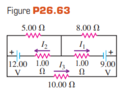
I tried doing three loops. For the bottom I did 9-I1(1) + I2(1) - I3(10) -12 = 0, for the upper left corner I did 12 - I2(1)- I2(5) = 0, for the upper right corner I did 9 - I1(1) - I1(8) = 0. I came to I1 =1, I2 =2 and I3 = .2. This was incorrect, I don't think I am summing the currents correctly. I have attached an image of the problem.
 

Attachments

  • Kirkoff Voltage Rule Problem.PNG
    Kirkoff Voltage Rule Problem.PNG
    5.4 KB · Views: 134
Physics news on Phys.org
Why do you have a term I1(8)? I1 is the current through the 1.00 Ω resistor. Is all that current also going through the 8.00 Ω resistor or does some of it split at the junction on the right? Same problem with the I2(5) term. To solve such circuits you need to make sure that charge is also conserved. This means that the net current through any junction must be zero.
 
Kindly see the attached pdf. My attempt to solve it, is in it. I'm wondering if my solution is right. My idea is this: At any point of time, the ball may be assumed to be at an incline which is at an angle of θ(kindly see both the pics in the pdf file). The value of θ will continuously change and so will the value of friction. I'm not able to figure out, why my solution is wrong, if it is wrong .
Thread 'Voltmeter readings for this circuit with switches'
TL;DR Summary: I would like to know the voltmeter readings on the two resistors separately in the picture in the following cases , When one of the keys is closed When both of them are opened (Knowing that the battery has negligible internal resistance) My thoughts for the first case , one of them must be 12 volt while the other is 0 The second case we'll I think both voltmeter readings should be 12 volt since they are both parallel to the battery and they involve the key within what the...
Back
Top